A retroreflector (sometimes called a retroflector or cataphote) is a device or surface that reflects radiation (usually light) back to its source with minimum scattering. This works at a wide range of angle of incidence, unlike a planar mirror,
which does this only if the mirror is exactly perpendicular to the wave
front, having a zero angle of incidence. Being directed, the
retroflector's reflection is brighter than that of a diffuse reflector. Corner reflectors and cat's eye reflectors are the most used kinds.
https://en.wikipedia.org/wiki/Retroreflector
A large relatively thin retroreflector can be formed by combining many small corner reflectors, using the standard hexagonal tiling.
https://en.wikipedia.org/wiki/Retroreflector
Corner reflector
Working principle of a corner reflector
Comparison
of the effect of corner (1) and spherical (2) retroreflectors on three
light rays. Reflective surfaces are drawn in dark blue.
A set of three mutually perpendicular reflective surfaces, placed to
form the internal corner of a cube, work as a retroreflector. The three
corresponding normal vectors of the corner's sides form a basis (x, y, z) in which to represent the direction of an arbitrary incoming ray, [a, b, c]. When the ray reflects from the first side, say x, the ray's x-component, a, is reversed to −a, while the y- and z-components
are unchanged. Therefore, as the ray reflects first from side x then
side y and finally from side z the ray direction goes from [a, b, c] to [−a, b, c] to [−a, −b, c] to [−a, −b, −c] and it leaves the corner with all three components of its direction exactly reversed.
Corner reflectors occur in two varieties. In the more common
form, the corner is literally the truncated corner of a cube of
transparent material such as conventional optical glass. In this
structure, the reflection is achieved either by total internal reflection
or silvering of the outer cube surfaces. The second form uses mutually
perpendicular flat mirrors bracketing an air space. These two types have
similar optical properties.
A large relatively thin retroreflector can be formed by combining many small corner reflectors, using the standard hexagonal tiling.
https://en.wikipedia.org/wiki/Retroreflector
Cat's eye
Eyeshine from retroreflectors of the transparent sphere type is clearly visible in this cat's eyes
Another common type of retroreflector consists of refracting optical
elements with a reflective surface, arranged so that the focal surface
of the refractive element coincides with the reflective surface,
typically a transparent sphere and (optionally) a spherical mirror. In the paraxial approximation, this effect can be achieved with lowest divergence with a single transparent sphere when the refractive index of the material is exactly one plus the refractive index ni of the medium from which the radiation is incident (ni
is around 1 for air). In that case, the sphere surface behaves as a
concave spherical mirror with the required curvature for
retroreflection. In practice, the optimal index of refraction may be
lower than ni + 1 ≅ 2 due
to several factors. For one, it is sometimes preferable to have an
imperfect, slightly divergent retroreflection, as in the case of road
signs, where the illumination and observation angles are different. Due
to spherical aberration,
there also exists a radius from the centerline at which incident rays
are focused at the center of the rear surface of the sphere. Finally,
high index materials have higher Fresnel reflection coefficients, so the
efficiency of coupling of the light from the ambient into the sphere
decreases as the index becomes higher. Commercial retroreflective beads
thus vary in index from around 1.5 (common forms of glass) up to around
1.9 (commonly barium titanate glass).
The spherical aberration problem with the spherical cat's eye can
be solved in various ways, one being a spherically symmetrical index
gradient within the sphere, such as in the Luneburg lens design. Practically, this can be approximated by a concentric sphere system.[2]
Because the back-side reflection for an uncoated sphere is
imperfect, it is fairly common to add a metallic coating to the back
half of retroreflective spheres to increase the reflectance, but this
implies that the retroreflection only works when the sphere is oriented
in a particular direction.
An alternative form of the cat's eye retroreflector uses a normal
lens focused onto a curved mirror rather than a transparent sphere,
though this type is much more limited in the range of incident angles
that it retroreflects.
The term cat's eye derives from the resemblance of the
cat's eye retroreflector to the optical system that produces the
well-known phenomenon of "glowing eyes" or eyeshine in cats and other vertebrates (which are only reflecting light, rather than actually glowing). The combination of the eye's lens and the cornea form the refractive converging system, while the tapetum lucidum behind the retina
forms the spherical concave mirror. Because the function of the eye is
to form an image on the retina, an eye focused on a distant object has a
focal surface that approximately follows the reflective tapetum lucidum structure,[citation needed] which is the condition required to form a good retroreflection.
This type of retroreflector can consist of many small versions of
these structures incorporated in a thin sheet or in paint. In the case
of paint containing glass beads, the paint adheres the beads to the
surface where retroreflection is required and the beads protrude, their
diameter being about twice the thickness of the paint.
Phase-conjugate mirror
A third, much less common way of producing a retroreflector is to use the nonlinear optical phenomenon of phase conjugation. This technique is used in advanced optical systems such as high-power lasers and optical transmission lines. Phase-conjugate mirrors[3]
reflects an incoming wave so that the reflected wave exactly follows
the path it has previously taken, and require a comparatively expensive
and complex apparatus, as well as large quantities of power (as
nonlinear optical processes can be efficient only at high enough
intensities). However, phase-conjugate mirrors have an inherently much
greater accuracy in the direction of the retroreflection, which in
passive elements is limited by the mechanical accuracy of the
construction.
https://en.wikipedia.org/wiki/Retroreflector

"Aura" around the shadow of a hot-air balloon, caused by retroreflection from dewdrops

"Aura" around the shadow of a hot-air balloon, caused by retroreflection from dewdrops
https://en.wikipedia.org/wiki/Retroreflector#/media/File:Balloon_shadow.jpg
Free-space optical communication
Modulated
retroreflectors, in which the reflectance is changed over time by some
means, are the subject of research and development for free-space optical communications
networks. The basic concept of such systems is that a low-power remote
system, such as a sensor mote, can receive an optical signal from a base
station and reflect the modulated signal back to the base station.
Since the base station supplies the optical power, this allows the
remote system to communicate without excessive power consumption.
Modulated retroreflectors also exist in the form of modulated
phase-conjugate mirrors (PCMs). In the latter case, a "time-reversed"
wave is generated by the PCM with temporal encoding of the
phase-conjugate wave (see, e.g., SciAm, Oct. 1990, "The Photorefractive
Effect," David M. Pepper, et al.).
Inexpensive corner-aiming retroreflectors are used in
user-controlled technology as optical datalink devices. Aiming is done
at night, and the necessary retroreflector area depends on aiming
distance and ambient lighting from street lamps. The optical receiver
itself behaves as a weak retroreflector because it contains a large,
precisely focused lens that detects illuminated objects in its focal plane. This allows aiming without a retroreflector for short ranges.
Other uses
Retroreflectors are used in the following example applications:
- In common (non-SLR) digital cameras, the sensor system is often
retroreflective. Researchers have used this property to demonstrate a
system to prevent unauthorized photographs by detecting digital cameras
and beaming a highly focused beam of light into the lens.[25]
- In movie screens to allow for high brilliance under dark conditions.[26]
- Digital compositing programs and chroma key
environments use retroreflection to replace traditional lit backdrops
in composite work as they provide a more solid colour without requiring
that the backdrop be lit separately.[27]
- In Longpath-DOAS
systems retroreflectors are used to reflect the light emitted from a
lightsource back into a telescope. It is then spectrally analyzed to
obtain information about the trace gas content of the air between the
telescope and the retro reflector.
- Barcode labels can be printed on retroreflective material to increase the range of scanning up to 50 feet.[28]
- In a form of 3D display; where a retro-reflective sheeting and a set of projectors is used to project stereoscopic images back to user's eye. The use of mobile projectors and positional tracking mounted on user's spectacles frame allows the illusion of a hologram to be created for computer generated imagery.[29][30][31]
- Flashlight fish of the family Anomalopidae have natural retroreflectors. See tapetum lucidum.
https://en.wikipedia.org/wiki/Retroreflector
Heiligenschein (German: [ˈhaɪlɪɡn̩ˌʃaɪn]; lit. 'halo, aureola') is an optical phenomenon in which a bright spot appears around the shadow of the viewer's head in the presence of dew. In photogrammetry and remote sensing, it is more commonly known as the hotspot. It is also occasionally known as Cellini's halo after the Italian artist and writer Benvenuto Cellini (1500–1571), who described the phenomenon in his memoirs in 1562.[1]
Nearly spherical dew droplets act as lenses to focus the light onto the surface behind them. When this light scatters
or reflects off that surface, the same lens re-focuses that light into
the direction from which it came. This configuration is sometimes called
a cat's eye retroreflector. Any retroreflective surface is brightest around the antisolar point.
Opposition surge by other particles than water and the glory in water vapour are similar effects caused by different mechanisms.

Heiligenschein, or hotspot, around the shadow of a
hot-air balloon cast on a field of standing crops (
Oxfordshire, England)
https://en.wikipedia.org/wiki/Heiligenschein
A 22° halo around the Sun, observed over
Bretton Woods, New Hampshire, USA on February 13, 2021
https://en.wikipedia.org/wiki/Halo_(optical_phenomenon)
Optical phenomena are any observable events that result from the interaction of light and matter.
All optical phenomena coincide with quantum phenomena.[1]
Common optical phenomena are often due to the interaction of light from
the sun or moon with the atmosphere, clouds, water, dust, and other
particulates. One common example is the rainbow, when light from the sun is reflected and refracted by water droplets. Some phenomena, such as the green ray, are so rare they are sometimes thought to be mythical.[2] Others, such as Fata Morganas, are commonplace in favored locations.
Other phenomena are simply interesting aspects of optics, or optical effects. For instance, the colors generated by a prism are often shown in classrooms.

A
22° halo around the Moon in
Atherton, California https://en.wikipedia.org/wiki/Optical_phenomena
A Fata Morgana (Italian: [ˈfaːta morˈɡaːna]) is a complex form of superior mirage visible in a narrow band right above the horizon. The term Fata Morgana is the Italian translation of "Morgan the Fairy" (Morgan le Fay of Arthurian legend). These mirages are often seen in the Italian Strait of Messina, and were described as fairy castles in the air or false land conjured by her magic.
Fata Morgana mirages significantly distort the object or objects
on which they are based, often such that the object is completely
unrecognizable. A Fata Morgana may be seen on land or at sea, in polar
regions, or in deserts. It may involve almost any kind of distant
object, including boats, islands, and the coastline. Often, a Fata
Morgana changes rapidly. The mirage comprises several inverted (upside
down) and erect (right-side up) images that are stacked on top of one
another. Fata Morgana mirages also show alternating compressed and
stretched zones.[1]
The optical phenomenon occurs because rays of light bend when they pass through air layers of different temperatures in a steep thermal inversion where an atmospheric duct has formed.[1]
In calm weather, a layer of significantly warmer air may rest over
colder dense air, forming an atmospheric duct that acts like a
refracting lens,
producing a series of both inverted and erect images. A Fata Morgana
requires a duct to be present; thermal inversion alone is not enough to
produce this kind of mirage. While a thermal inversion often takes place
without there being an atmospheric duct, an atmospheric duct cannot
exist without there first being a thermal inversion.

A
Fata Morgana seen over the Baltic Sea, 2016. The mirage consists of
multiple upright and inverted images over the original object

A Fata Morgana of a cargo ship seen off the coast of Oceanside, California
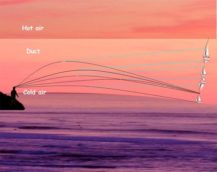
Schematic diagram explaining the Fata Morgana mirage
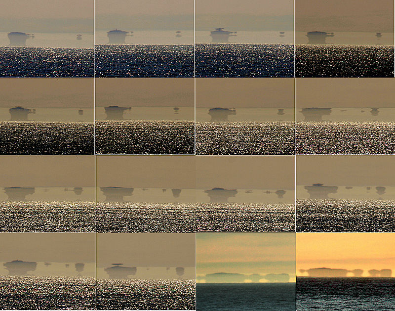
A sequence of a Fata Morgana of the Farallon Islands as seen from San Francisco

The above sequence as an animation.
https://en.wikipedia.org/wiki/Fata_Morgana_(mirage)
Observing a Fata Morgana
Schematic diagram explaining the Fata Morgana mirage
A Fata Morgana is most commonly seen in polar regions,
especially over large sheets of ice that have a uniform low
temperature. It may, however, be observed in almost any area. In polar
regions the Fata Morgana phenomenon is observed on relatively cold days.
In deserts, over oceans, and over lakes, however, a Fata Morgana may be
observed on hot days.
To generate the Fata Morgana phenomenon, the thermal inversion has to be strong enough that the curvature of the light rays within the inversion layer is stronger than the curvature of the Earth.[1] Under these conditions, the rays bend and create arcs. An observer needs to be within or below an atmospheric duct in order to be able to see a Fata Morgana.[2] Fata Morgana may be observed from any altitude within the Earth's atmosphere, from sea level up to mountaintops, and even including the view from airplanes.[3][4]
The above sequence as an animation.
A Fata Morgana may be described as a very complex superior mirage with more than three distorted erect and inverted images.[1]
Because of the constantly changing conditions of the atmosphere, a Fata
Morgana may change in various ways within just a few seconds of time,
including changing to become a straightforward superior mirage. The
sequential image here shows sixteen photographic frames of a mirage of
the Farallon Islands
as seen from San Francisco; the images were all taken on the same day.
In the first fourteen frames, elements of the Fata Morgana mirage
display alternations of compressed and stretched zones.[1]
The last two frames were photographed a few hours later, around sunset
time. At that point in time, the air was cooler while the ocean was
probably a little bit warmer, which caused the thermal inversion
to be not as extreme as it was few hours before. A mirage was still
present at that point, but it was not so complex as a few hours before
sunset: the mirage was no longer a Fata Morgana, but instead had become a
simple superior mirage.
Fata Morgana mirages are visible to the naked eye, but in order
to be able to see the detail within them, it is best to view them
through binoculars, a telescope, or as is the case in the images here, through a telephoto lens. Gabriel Gruber (1740–1805) and Tobias Gruber [sl] (1744–1806), who observed Fata Morgana above Lake Cerknica, were the first to study it in a laboratory setting.
https://en.wikipedia.org/wiki/Fata_Morgana_(mirage)
Etymology
La Fata Morgana ("The Fairy Morgana") is the Italian name of Morgan le Fay, also known as Morgana and other variants, who was described as a powerful sorceress in the Arthurian legend. As her name indicates, the figure of Morgan appears to have been originally a fairy
figure rather than a human woman. The early works featuring Morgan do
not elaborate on her nature, other than describing her role as that of a
fairy or magician. Later, she was described as a
King Arthur's half-sister and an enchantress.[5] After King Arthur's final battle at Camlann, Morgan takes her half-brother Arthur to Avalon.[6] In medieval times, suggestions for the location of Avalon included the other side of the Earth at the antipodes, Sicily, and other locations in the Mediterranean.[7] Legends claimed that sirens in the waters around Sicily lured the unwary to their death. Morgan is associated not only with Sicily's Mount Etna (the supposedly hollow mountain locally identified as Avalon since the 12th century[8]), but also with sirens. In a medieval French Arthurian romance of the 13th century, Floriant et Florete, she is called "mistress of the fairies of the salt sea" (La mestresse [des] fées de la mer salée).[9] Ever since that time, Fata Morgana has been associated with Sicily in the Italian folklore and literature.[10] For example, a local legend connects Morgan and her magical mirages with Roger I of Sicily and the Norman conquest of the island from the Arabs.[11][12]
An 1844 drawing entitled The Fata Morgana, As Observed in the Harbour of Messina
Walter Charleton,
in his 1654 treatise "Physiologia Epicuro-Gassendo-Charltoniana",
devotes several pages to the description of the Morgana of Rhegium, in
the Strait of Messina (Book III, Chap. II, Sect. II). He records that a
similar phenomenon was reported in Africa by Diodorus Siculus, a Greek historian writing in the first century BC, and that the Rhegium Fata Morgana was described by Damascius, a Greek philosopher of the sixth century AD. In addition, Charleton tells us that Athanasius Kircher described the Rhegium mirage in his book of travels.
An early mention of the term Fata Morgana in English, in 1818, referred to such a mirage noticed in the Strait of Messina, between Calabria and Sicily.[13]
- Fata Morgana, phr. : It. : a peculiar mirage occasionally seen
on the coasts of the Straits of Messina, locally attributed to a fay
Morgana. Hence, metaph. any illusory appearance. 1818 In mountainous
regions, deceptions of sight, Fata Morgana, &c., are more common: In
E. Burl's Lett. N. Scotl., Vol. II. p. in (1818).
https://en.wikipedia.org/wiki/Fata_Morgana_(mirage)
Famous legends and observations
The Flying Dutchman
The Flying Dutchman, according to folklore, is a ghost ship that can never go home, and is doomed to sail the seven seas forever. The Flying Dutchman
is usually spotted from afar, sometimes seen to be glowing with ghostly
light. One of the possible explanations of the origin of the Flying Dutchman legend is a Fata Morgana mirage seen at sea.[14]
A
nineteenth-century book illustration, showing enlarged superior
mirages; mirages can never be so far above the horizon, and a superior
mirage can never increase the length of an object as shown on the right
A Fata Morgana superior mirage of a ship can take many different
forms. Even when the boat in the mirage does not seem to be suspended in
the air, it still looks ghostly, and unusual, and what is even more
important, it is ever-changing in its appearance. Sometimes a Fata
Morgana causes a ship to appear to float inside the waves, at other
times an inverted ship appears to sail above its real companion.
In fact, with a Fata Morgana it can be hard to say which
individual segment of the mirage is real and which is not real: when a
real ship is out of sight because it is below the horizon line, a Fata
Morgana can cause the image of it to be elevated, and then everything
which is seen by the observer is a mirage. On the other hand, if the
real ship is still above the horizon, the image of it can be duplicated
many times and elaborately distorted by a Fata Morgana.
The appearance of two ships changing owing to the Fata Morgana phenomenon: the four frames in the first column are of ship No. 1, and the four frames in the second column are of ship No. 2
In this mirage, at least three separate images of a boat are visible.
The real one at the bottom and the uppermost one are in the upright
position, whereas the one in the middle is inverted
Superimposed detail from six frames of a view showing how the miraged image of a ship changes from one moment to the next
Phantom islands
A Fata Morgana of the sea surface and
sun glitter, with a boat at the left hand side of the image
In the 19th and early 20th centuries, Fata Morgana mirages may have played a role in a number of unrelated "discoveries" of arctic and antarctic land masses which were later shown not to exist.[citation needed] Icebergs frozen into the pack ice, or the uneven surface of the ice itself, may have contributed to the illusion of distant land features.
Sannikov Land
Yakov Sannikov and Matvei Gedenschtrom claimed to have seen a land mass north of Kotelny Island during their 1809–1810 cartographic expedition to the New Siberian Islands. Sannikov reported this sighting of a "new land" in 1811, and the supposed island was named after him.[15] Three-quarters of a century later, in 1886, Baron Eduard Toll, a Baltic German
explorer in Russian service, reported observing Sannikov Land during
another expedition to the New Siberian Islands. In 1900, he would lead still another expedition to the region, which had among its objectives the location and exploration of Sannikov Land.[16] The expedition was unsuccessful in this respect.[17]
Toll and three others were lost after they departed their ship, which
was stuck in ice for the winter, and embarked on a risky expedition by
dog sled.[18] In 1937, the Soviet icebreaker Sadko also tried and failed to find Sannikov Land.[19] Some historians and geographers have theorised that the land mass that Sannikov and Toll saw was actually Fata Morganas of Bennett Island.[15]
Croker Mountains
In 1818, Sir John Ross led an expedition to discover the long-sought-after Northwest Passage. When he reached Lancaster Sound
in Canada, he sighted, in the distance, a land mass with mountains,
directly ahead in the ship's course. He named the mountain range the
Croker Mountains,[20] after First Secretary to the Admiralty John Wilson Croker, and ordered the ship to turn around and return to England. Several of his officers protested, including First Mate William Edward Parry and Edward Sabine, but they could not dissuade him.[21]
The account of Ross's voyage, published a year later, brought to light
this disagreement, and the ensuing controversy over the existence of the
Croker Mountains ruined Ross's reputation. The year after Ross's
expedition, in 1819, Parry was given command of his own Arctic
expedition, and proved Ross wrong by continuing west beyond where Ross
had turned back, and sailing through the supposed location of the Croker
Mountains. The mountain range that had caused Ross to abandon his
mission had been a mirage.
Ross made two errors. First, he refused to listen to the counsel
of his officers, who may have been more familiar with mirages than he
was. Second, his attempt to honour Croker by naming a mountain range
after him backfired when the mountains turned out to be non-existent.
Ross could not obtain ships, or funds, from the government for his
subsequent expeditions, and was forced to rely on private backers
instead.[22]
New South Greenland
Benjamin Morrell
reported that, in March 1823, while on a voyage to the Antarctic and
southern Pacific Ocean, he had explored what he thought was the east
coast of New South Greenland.[23] The west coast of New South Greenland had been explored two years earlier by Robert Johnson, who had given the land its name.[24] This name was not adopted, however, and the area, which is the northern part of the Antarctic Peninsula, is now known as Graham Land.[25] Morrell's reported position was actually far to the east of Graham Land.[26]
Searches for the land that Morrell claimed to have explored would
continue into the early 20th century before New South Greenland's
existence was conclusively disproven. Why Morrell reported exploring a
non-existent land is unclear, but one possibility is that he mistook a
Fata Morgana for actual land.[27]
Crocker Land
Robert Peary
claimed to have seen, while on a 1906 Arctic expedition, a land mass in
the distance. He said that it was north-west from the highest point of Cape Thomas Hubbard, which is situated in what is now the northern Canadian territory of Nunavut,
and he estimated it to be 210 km (130 miles) away, at about 83 degrees
N, longitude 100 degrees W. He named it Crocker Land, after George
Crocker of the Peary Arctic Club.[28] As Peary's diary contradicts his public claim that he had sighted land,[29] it is now believed that Crocker Land was a fraudulent invention of Peary,[30] created in an unsuccessful attempt to secure further funding from Crocker.
In 1913, unaware that Crocker Land was merely an invention, Donald Baxter MacMillan
organised the Crocker Land Expedition, which set out to reach and
explore the supposed land mass. On 21 April, the members of the
expedition did, in fact, see what appeared to be a huge island on the
north-western horizon. As MacMillan later said, "Hills, valleys,
snow-capped peaks extending through at least one hundred and twenty
degrees of the horizon". Piugaattoq, a member of the expedition and an
Inuit hunter with 20 years of experience of the area, explained that it
was just an illusion. He called it poo-jok, which means 'mist'.
However, MacMillan insisted that they press on, even though it was late
in the season and the sea ice was breaking up. For five days they went
on, following the mirage. Finally, on 27 April, after they had covered
some 200 km (125 miles) of dangerous sea ice, MacMillan was forced to
admit that Piugaattoq was right—the land that they had sighted was in
fact a mirage (probably a Fata Morgana). Later, MacMillan wrote:
from
Four Years in the White North[31]
The day was exceptionally clear, not a cloud or trace of mist; if
land could be seen, now was our time. Yes, there it was! It could even
be seen without a glass, extending from southwest true to
north-northeast. Our powerful glasses, however, brought out more clearly
the dark background in contrast with the white, the whole resembling
hills, valleys and snow-capped peaks to such a degree that, had we not
been out on the frozen sea for 150 miles [240 km], we would have staked
our lives upon its reality. Our judgment then, as now, is that this was a
mirage or loom of the sea ice.
The expedition collected interesting samples, but is still considered to
be a failure and a very expensive mistake. The final cost was $100,000
(equivalent to $2,000,000 in 2021).[32]
Hy Brasil
Hy Brasil
is an island that was said to appear once every few years off the coast
of Co. Kerry, Ireland. Hy Brasil has been drawn on ancient maps as a
perfectly circular island with a river running directly through it.
Lake Ontario
Lake Ontario is said to be famous for mirages, with opposite shorelines becoming clearly visible during the events.[33]
In July 1866, mirages of boats and islands were seen from Kingston, Ontario.[34]
A Mirage – The atmospheric phenomenon known as "mirage" might have
been observed on Sunday evening between 6 and 7 o'clock, by looking
towards the lake. The line beyond which this phenomenon was observable
seemed to strike from about the middle portion of Amherst Island across
to the southeast, for while the lower half of the island presented its
usual appearance, the upper half was unnaturally distorted and thrown
upward in columnar shape with an apparent height of two to three hundred
feet. The upper line or cloud from this elevation stretched southward,
upon which was thrown the image of objects. A barque sailing in front of
this cloud presented a double appearance. While she appeared slightly
distorted on the surface of the water, her image was inverted upon the
background of the cloud referred to, and both blending together produced
a curious sight. At the same time the ship and its shadow were again
repeated in a more shadowy form, but distinct, in the foreground, the
base being a line of smooth water. Another bark whose hull was entirely
below the horizon, the topsails alone being visible, had its hull
shadowed on this foreground, but no inversion in this case could be
observed. It may be added that these optical phenomena in regard to the
vessels could only be seen with the aid of a telescope, for the nearest
vessel was at the time fully sixteen miles [26 km] distant. The
phenomena lasted over an hour, the illusion changing every moment in its
character.
Here the described mirages of vessels "could only be seen with the aid of a telescope". It is often the case when observing a Fata Morgana that one needs to use a telescope or binoculars to really make out the mirage. The "cloud" that the article mentions a few times probably refers to a duct.
On 25 August 1894, Scientific American described a "remarkable mirage" seen by the citizens of Buffalo, New York.[35][36]
The people of Buffalo, N.Y., were treated to a remarkable mirage,
between ten and eleven o'clock, on the morning of 16 August, [1894]. It
was the city of Toronto with its harbor and small island to the south of
the city. Toronto is fifty-six miles [90 km] from Buffalo, but the
church spires could be counted with the greatest ease. The mirage took
in the whole breadth of Lake Ontario, Charlotte, the suburbs of
Rochester, being recognized as a projection east of Toronto. A
side–wheel steamer could be seen traveling in a line from Charlotte to
Toronto Bay. Two dark objects were at last found to be the steamers of
the New York Central plying between Lewiston and Toronto. A sail-boat
was also visible and disappeared suddenly. Slowly the mirage began to
fade away, to the disappointment of thousands who crowded the roofs of
houses and office buildings. A bank of clouds was the cause of the
disappearance of the mirage. A close examination of the map showed the
mirage did not cause the slightest distortion, the gradual rise of the
city from the water being rendered perfectly. It is estimated that at
least 20,000 spectators saw the novel spectacle.
This mirage is what is known as that of the third order; that is,
the object looms up far above the level and not inverted, as with
mirages of the first and second orders, but appearing like a perfect
landscape far away in the sky.
Scientific American, 25 August 1894.
This description might refer to looming owing to inversion rather than to an actual mirage.
McMurdo Sound and Antarctica
From McMurdo Station in Antarctica, Fata Morganas are often seen during the Antarctic spring and summer, across McMurdo Sound.[37][38][39] An Antarctic Fata Morgana, seen from a C-47 transport flight, was recounted:
We were going along smoothly and all of a sudden a mountain peak
seemed to rise up out of nowhere up ahead. We looked again and it was
gone. A couple of minutes later it popped up again rising some 300 feet
higher than our altitude. We never seemed to get any closer to it. The
peak just kept popping up and down, getting higher and higher and higher
every time it reappeared.
Rear Adm. Fred E. Bakutis, commanding the Antarctic Navy Support Activities[37]
UFOs
A Fata Morgana distorting the images of distant boats beyond recognition
Fata Morgana mirages may continue to trick some observers and are still sometimes mistaken for otherworldly objects such as UFOs.[40] A Fata Morgana can display an object that is located below the astronomical horizon
as an apparent object hovering in the sky. A Fata Morgana can also
magnify such an object vertically and make it look absolutely
unrecognizable.
Some UFOs which are seen on radar may also be due to Fata Morgana mirages. Official UFO investigations in France indicate:
As is well known, atmospheric ducting is the explanation for certain
optical mirages, and in particular the arctic illusion called "fata
morgana" where distant ocean or surface ice, which is essentially flat,
appears to the viewer in the form of vertical columns and spires, or
"castles in the air".
People often assume that mirages occur only rarely. This may be
true of optical mirages, but conditions for radar mirages are more
common, due to the role played by water vapor which strongly affects the
atmospheric refractivity in relation to radio waves. Since clouds are
closely associated with high levels of water vapor, optical mirages due
to water vapor are often rendered undetectable by the accompanying
opaque cloud. On the other hand, radar propagation is essentially
unaffected by the water droplets of the cloud so that changes in water
vapor content with altitude are very effective in producing atmospheric
ducting and radar mirages.[41]
Australia
Fata Morgana mirages could explain the mysterious Australian Min Min light phenomenon.[42]
This would also explain the way in which the legend has changed over
time: The first reports were of a stationary light, which in a Fata
Morgana effect would be an image of a campfire. In more recent reports
this has changed to moving lights, which in an inversion reflection such
as Fata Morgana would be headlights over the horizon being reflected by
the inversion.
Greenland
Fata Morgana Land is a phantom island in the Arctic, reported first in 1907. After an unfruitful search, it was deemed to be Tobias Island.[43]
In literature
A Fata Morgana is usually associated with something mysterious, something that never could be approached.[44]
An unrealistic 1886 drawing of a "Fata Morgana" mirage in a
desert
O sweet illusions of song
That tempt me everywhere,
In the lonely fields, and the throng
Of the crowded thoroughfare!
I approach and ye vanish away,
I grasp you, and ye are gone;
But ever by night and by day,
The melody soundeth on.
As the weary traveler sees
In desert or prairie vast,
Blue lakes, overhung with trees
That a pleasant shadow cast;
Fair towns with turrets high,
And shining roofs of gold,
That vanish as he draws nigh,
Like mists together rolled—
So I wander and wander along,
And forever before me gleams
The shining city of song,
In the beautiful land of dreams.
But when I would enter the gate
Of that golden atmosphere,
It is gone, and I wonder and wait
For the vision to reappear.
In the lines, "the weary traveller sees / In desert or prairie vast, /
Blue lakes, overhung with trees / That a pleasant shadow cast", because
of the mention of blue lakes, it is clear that the author is actually
describing not a Fata Morgana, but rather a common inferior or desert
mirage. The 1886 drawing shown here of a "Fata Morgana" in a desert
might have been an imaginative illustration for the poem, but in reality
no mirage ever looks like this. Andy Young writes, "They're always
confined to a narrow strip of sky—less than a finger's width at arm's
length—at the horizon."[1]
The 18th-century poet Christoph Martin Wieland
wrote about "Fata Morgana's castles in the air". The idea of castles in
the air was probably so irresistible that many languages still use the
phrase Fata Morgana to describe a mirage.[9]
In the book Thunder Below! about the submarine USS Barb,
the crew sees a Fata Morgana (called an "arctic mirage" in the book) of
four ships trapped in the ice. As they try to approach the ships the
mirage vanishes.[46]
The Fata Morgana is briefly mentioned in the 1936 H. P. Lovecraft horror novel At the Mountains of Madness,
in which the narrator states: "On many occasions the curious
atmospheric effects enchanted me vastly; these including a strikingly
vivid mirage—the first I had ever seen—in which distant bergs became the
battlements of unimaginable cosmic castles."
See also
https://en.wikipedia.org/wiki/Fata_Morgana_(mirage)
A Brocken spectre (British English; American spelling: Brocken specter; German: Brockengespenst), also called Brocken bow, mountain spectre, or spectre of the Brocken is the magnified (and apparently enormous) shadow of an observer cast in mid air upon any type of cloud opposite a strong light source. Additionally, if the cloud consists of water droplets backscattered, a bright area called Heiligenschein, and halo-like rings of rainbow coloured light called a glory can be seen around the head or apperature silhouette of the spectre. Typically the spectre appears in sunlight opposite the sun's direction at the antisolar point.
The phenomenon can appear on any misty mountainside, cloud bank, or be seen from an aircraft, but the frequent fogs and low-altitude accessibility of the Brocken, a peak in the Harz Mountains in Germany, have created a local legend from which the phenomenon draws its name. The Brocken spectre was observed and described by Johann Silberschlag in 1780, and has often been recorded in literature about the region.

A Brocken spectre within
glory rings
Occurrence
A semi-artificial Brocken spectre created by standing in front of the headlight of a car, on a foggy night.
The "spectre" appears when the sun shines from behind the observer, who is looking down from a ridge or peak into mist or fog.[1] The light projects their shadow through the mist, often in a triangular shape due to perspective.[2] The apparent magnification of size of the shadow is an optical illusion
that occurs when the observer judges their shadow on relatively nearby
clouds to be at the same distance as faraway land objects seen through
gaps in the clouds, or when there are no reference points by which to
judge its size. The shadow also falls on water droplets of varying distances from the eye, confusing depth perception.
The ghost can appear to move (sometimes suddenly) because of the
movement of the cloud layer and variations in density within the cloud.
References in popular culture and the arts
Samuel Taylor Coleridge's poem "Constancy to an Ideal Object" concludes with an image of the Brocken spectre:
And art thou nothing? Such thou art, as when
The woodman winding westward up the glen
At wintry dawn, where o'er the sheep-track's maze
The viewless snow-mist weaves a glist'ning haze,
Sees full before him, gliding without tread,
An image with a glory round its head;
The enamoured rustic worships its fair hues,
Nor knows he makes the shadow he pursues!
Another night Brocken spectre created by headlights of a car.
Lewis Carroll's "Phantasmagoria"
includes a line about a Spectre who "...tried the Brocken business
first/but caught a sort of chill/so came to England to be nursed/and
here it took the form of thirst/which he complains of still."
Stanisław Lem's Fiasco
(1986) has a reference to the "Brocken Specter": "He was alone. He had
been chasing himself. Not a common phenomenon, but known even on Earth.
The Brocken Specter in the Alps, for example." The situation, of
pursuing one's self, via a natural illusion is a repeated theme in Lem. A
scene of significance in his book The Investigation
(1975) depicts a detective who, within the confines of a snowy,
dead-end alley, confronts a man who turns out to be the detective's own
reflection, "The stranger... was himself. He was standing in front of a
huge mirrored wall marking the end of the arcade."
In The Radiant Warrior (1989), part of Leo Frankowski's Conrad Stargard series, the protagonist uses the Brocken Spectre to instill confidence in his recruits.
The Brocken spectre is a key trope in Paul Beatty's The White Boy Shuffle
(1996), in which a character, Nicholas Scoby, declares that his dream
(he specifically calls it a "Dream and a half, really") is to see his
glory through a Brocken spectre (69).
In James Hogg's novel The Private Memoirs and Confessions of a Justified Sinner (1824) the Brocken spectre is used to suggest psychological horror.
Shadow of an aeroplane cast by the sun on nearby clouds
Brocken spectre observed from an aeroplane.
A solar glory and brocken spectre from
Crib Goch in 2008
Carl Jung in Memories, Dreams, Reflections wrote:
... I had a dream which both frightened and encouraged me. It was night
in some unknown place, and I was making slow and painful headway against
a mighty wind. Dense fog was flying along everywhere. I had my hands
cupped around a tiny light which threatened to go out at any moment...
Suddenly I had the feeling that something was coming up behind me. I
looked back, and saw a gigantic black figure following me... When I
awoke I realized at once that the figure was a "specter of the Brocken,"
my own shadow on the swirling mists, brought into being by the little
light I was carrying.[3]
In Gravity's Rainbow, Geli Tripping and Slothrop make "god-shadows" from a Harz precipice, as Walpurgisnacht
wanes to dawn. Additionally, the French–Canadian quadruple agent Rémy
Marathe muses episodically about the possibility of witnessing the
fabled spectre on the mountains of Tucson in David Foster Wallace's novel Infinite Jest.
The explorer Eric Shipton saw a Brocken Spectre during his first ascent of Nelion on Mount Kenya with Percy Wyn-Harris and Gustav Sommerfelt in 1929. He wrote:
Then the towering buttresses of Batian and Nelion
appeared; the rays of the setting sun broke through and, in the east,
sharply defined, a great circle of rainbow colours framed our own
silhouettes. It was the only perfect Brocken Spectre I have ever seen.[4]
The progressive metal band Fates Warning makes numerous references to the Brocken Spectre in both their debut album title Night on Bröcken and in lyrics on a subsequent song called "The Sorceress" from the album Awaken the Guardian that read "Through the Brocken Spectre rose a luring Angel."
The design of Kriemhild Gretchen, a Witch in the anime series Puella Magi Madoka Magica, may have been inspired by the Brocken spectre.[5]
In Charles Dickens's Little Dorrit,
Book II Chapter 23, Flora Finching, in the course of one of her
typically free-associative babbles to Mr Clennam, says " ... ere yet Mr F
appeared a misty shadow on the horizon paying attentions like the
well-known spectre of some place in Germany beginning with a B ... "
"Brocken Spectre" is the title of a track on David Tipper's 2010 album Broken Soul Jamboree.
In the manga and anime Tensou Sentai Goseiger, Brocken Spectres were one of the enemies that Gosei Angels must face.
In the manga One Piece, Brocken spectres make an appearance in the Skypiea story arc.
In the anime Detective Conan, Brocken spectres are mentioned in episode 348 and episode 546 as well.
In "The Problem of Pain" by C.S. Lewis the Brocken spectre is mentioned in the chapter "Heaven".
In chapter 12 of Whose Body? (Lord Peter Wimsey) by Dorothy L. Sayers.
See also
- Diffraction
- Earth's shadow, the shadow that the Earth itself casts on its atmosphere
- Am Fear Liath Mòr, "Big Grey Man" in Scottish Gaelic, a supposed supernatural being found on Scotland's second-highest peak, Ben Macdhui
- Dark Watchers, supposed supernatural beings seen along the crest of the Santa Lucia Mountains, in California
- Gegenschein
- Glory (optical phenomenon)
- Heiligenschein, an optical phenomenon which creates a bright spot around the shadow of the viewer's head
- Opposition surge, the brightening of a rough surface, or an object with many particles, when illuminated from directly behind the observer
References
McKenzie, Steven (17 February 2015). "Shades of grey: What is the brocken spectre". BBC News Online. Retrieved 3 January 2020.
"Brocken spectre". atoptics.co.uk.
Jung, Carl; Jaffé, Aniela (1989). Memories, Dreams, Reflections. Vintage. p. 88.
Shipton, Eric (1969). That Untravelled World. Hodder and Stoughton. pp. 55–56.
Further reading
External links
https://en.wikipedia.org/wiki/Brocken_spectre
While
mirages are the best known
atmospheric refraction phenomena,
looming and similar refraction phenomena
do not produce mirages. Mirages show an extra image or images of the
miraged object, while looming, towering, stooping, and sinking do not.
No inverted image is present in those phenomena either. Depending on
atmospheric conditions, the objects can appear to be elevated or
lowered, stretched or stooped. These phenomena can occur together,
changing the appearance of different parts of the objects in different
ways. Sometimes these phenomena can occur together with a true mirage.
[1][2]
The distant boats appear to be floating in the sky as a result of looming and other refraction phenomena.
https://en.wikipedia.org/wiki/Looming_and_similar_refraction_phenomena
The green flash and green ray are meteorological optical phenomena that sometimes occur transiently around the moment of sunset or sunrise. When the conditions are right, a distinct green spot is briefly visible above the Sun's upper limb;
the green appearance usually lasts for no more than two seconds.
Rarely, the green flash can resemble a green ray shooting up from the
sunset or sunrise point.
Green flashes occur because the Earth's atmosphere can cause the light from the Sun to separate, or refract,
into different colors. Green flashes are a group of similar phenomena
that stem from slightly different causes, and therefore, some types of
green flashes are more common than others.[1]

The development of a green flash at sunset in San Francisco

A green flash in
Santa Cruz, California https://en.wikipedia.org/wiki/Green_flash
Atmospheric optical phenomena
Non-atmospheric optical phenomena
Other optical effects
- Asterism, star gems such as star sapphire or star ruby
- Aura, a phenomenon in which gas or dust surrounding an object luminesces or reflects light from the object
- Aventurescence, also called the Schiller effect, spangled gems such as aventurine quartz and sunstone
- Baily's beads, grains of sunlight visible in total solar eclipses.
- camera obscura
- Cathodoluminescence
- Caustics
- Chatoyancy, cat's eye gems such as chrysoberyl cat's eye or aquamarine cat's eye
- Chromatic polarization
- Diffraction, the apparent bending and spreading of light waves when they meet an obstruction
- Dispersion
- Double refraction or birefringence of calcite and other minerals
- Double-slit experiment
- Electroluminescence
- Evanescent wave
- Fluorescence, also called luminescence or photoluminescence
- Mie scattering (Why clouds are white)
- Metamerism as of alexandrite
- Moiré pattern
- Newton's rings
- Phosphorescence
- Pleochroism gems or crystals, which seem "many-colored"
- Polarized light-related phenomena such as double refraction, or Haidinger's brush
- Rayleigh scattering (Why the sky is blue, sunsets are red, and associated phenomena)
- Reflection
- Refraction
- Sonoluminescence
- Synchrotron radiation
- The separation of light into colors by a prism
- Triboluminescence
- Thomson scattering
- Total internal reflection
- Twisted light
- Umov effect
- Zeeman effect
- The ability of light to travel through space or through a vacuum.
Entoptic phenomena
Optical illusions
Unexplained phenomena
Some phenomena are yet to be conclusively explained and may possibly be some form of optical phenomena. Some[weasel words] consider many of these "mysteries" to simply be local tourist attractions that are not worthy of thorough investigation.[4]
See also
https://en.wikipedia.org/wiki/Optical_phenomena
In folklore, a will-o'-the-wisp, will-o'-wisp or ignis fatuus (Latin for 'giddy flame'),[1] plural ignes fatui, is an atmospheric ghost light seen by travellers at night, especially over bogs, swamps or marshes. The phenomenon is known in English folk belief, English folklore and much of European folklore by a variety of names, including jack-o'-lantern, friar's lantern and hinkypunk, and is said to mislead travellers by resembling a flickering lamp or lantern.[2] In literature, will-o'-the-wisp metaphorically refers to a hope or goal that leads one on, but is impossible to reach, or something one finds strange or sinister.[3]
Wills-o'-the-wisp appear in folk tales and traditional legends of
numerous countries and cultures; notable wills-o'-the-wisp include St. Louis Light in Saskatchewan, the Spooklight in Southwestern Missouri and Northeastern Oklahoma, the Marfa lights of Texas, the Naga fireballs on the Mekong in Thailand, the Paulding Light in Upper Peninsula of Michigan and the Hessdalen light in Norway.
In urban legends, folklore and superstition, wills-o'-the-wisp are typically attributed to ghosts, fairies or elemental spirits. Modern science explains the light aspect as natural phenomena such as bioluminescence or chemiluminescence, caused by the oxidation of phosphine (PH3), diphosphane (P2H4) and methane (CH4) produced by organic decay.

The Will o' the Wisp and the Snake by
Hermann Hendrich (1854–1931)
https://en.wikipedia.org/wiki/Will-o%27-the-wisp
An optical vortex (also known as a photonic quantum vortex, screw dislocation or phase singularity) is a zero of an optical field; a point of zero intensity. The term is also used to describe a beam of light that has such a zero in it. The study of these phenomena is known as singular optics.

Diagram
of different modes, four of which are optical vortices. Columns show
the helical structures, phase-front and intensity of the beams
https://en.wikipedia.org/wiki/Optical_vortex
Synchrotron radiation (also known as magnetobremsstrahlung radiation) is the electromagnetic radiation emitted when relativistic charged particles are subject to an acceleration perpendicular to their velocity (a ⊥ v). It is produced artificially in some types of particle accelerators, or naturally by fast electrons moving through magnetic fields. The radiation produced in this way has a characteristic polarization and the frequencies generated can range over a large portion of the electromagnetic spectrum.[1]
Synchrotron radiation is similar to bremsstrahlung radiation,
which is emitted by a charged particle when the acceleration is
parallel to the direction of motion. The general term for radiation
emitted by particles in a magnetic field is gyromagnetic radiation,
for which synchrotron radiation is the ultra-relativistic special case.
Radiation emitted by charged particles moving non-relativistically in a
magnetic field is called cyclotron emission.[2] For particles in the mildly relativistic range (≈85% of the speed of light), the emission is termed gyro-synchrotron radiation.[3]
In astrophysics, synchrotron emission occurs, for instance, due to ultra-relativistic motion of a charged particle around a black hole.[4] When the source follows a circular geodesic around the black hole, the synchrotron radiation occurs for orbits close to the photosphere where the motion is in the ultra-relativistic regime.
https://en.wikipedia.org/wiki/Synchrotron_radiation
Sonoluminescence is the emission of light from imploding bubbles in a liquid when excited by sound.
Sonoluminescence was first discovered in 1934 at the University of Cologne.
It occurs when a sound wave of sufficient intensity induces a gaseous
cavity within a liquid to collapse quickly, emitting a burst of light.
The phenomenon can be observed in stable single-bubble sonoluminescence
(SBSL) and multi-bubble sonoluminescence (MBSL). In 1960, Peter Jarman
proposed that sonoluminescence is thermal in origin and might arise from
microshocks within collapsing cavities. Later experiments revealed that
the temperature inside the bubble during SBSL could reach up to 12,000
kelvins. The exact mechanism behind sonoluminescence remains unknown,
with various hypotheses including hotspot, bremsstrahlung , and collision-induced radiation. Some researchers[citation needed]
have even speculated that temperatures in sonoluminescing systems could
reach millions of kelvins, potentially causing thermonuclear fusion.
The phenomenon has also been observed in nature, with the pistol shrimp
being the first known instance of an animal producing light through
sonoluminescence.
History
The sonoluminescence effect was first discovered at the University of Cologne in 1934 as a result of work on sonar.[1] Hermann Frenzel and H. Schultes put an ultrasound transducer in a tank of photographic developer fluid.
They hoped to speed up the development process. Instead, they noticed
tiny dots on the film after developing and realized that the bubbles in
the fluid were emitting light with the ultrasound turned on.[2]
It was too difficult to analyze the effect in early experiments because
of the complex environment of a large number of short-lived bubbles.
This phenomenon is now referred to as multi-bubble sonoluminescence
(MBSL).
In 1960, Peter Jarman from Imperial College of London
proposed the most reliable theory of sonoluminescence phenomenon. He
concluded that sonoluminescence is basically thermal in origin and that
it might possibly arise from microshocks with the collapsing cavities.[3]
In 1989, an experimental advance was introduced which produced stable single-bubble sonoluminescence (SBSL).[citation needed]
In single-bubble sonoluminescence, a single bubble trapped in an
acoustic standing wave emits a pulse of light with each compression of
the bubble within the standing wave.
This technique allowed a more systematic study of the phenomenon,
because it isolated the complex effects into one stable, predictable
bubble. It was realized that the temperature inside the bubble was hot
enough to melt steel, as seen in an experiment done in 2012; the temperature inside the bubble as it collapsed reached about 12,000 kelvins.[4] Interest in sonoluminescence was renewed when an inner temperature of such a bubble well above one million kelvins was postulated.[5]
This temperature is thus far not conclusively proven; rather, recent
experiments indicate temperatures around 20,000 K (19,700 °C;
35,500 °F).[6]
Properties
Long exposure image of multi-bubble sonoluminescence created by a high-intensity
ultrasonic horn immersed in a beaker of liquid
Sonoluminescence can occur when a sound wave of sufficient intensity
induces a gaseous cavity within a liquid to collapse quickly. This
cavity may take the form of a pre-existing bubble, or may be generated
through a process known as cavitation.
Sonoluminescence in the laboratory can be made to be stable, so that a
single bubble will expand and collapse over and over again in a periodic
fashion, emitting a burst of light each time it collapses. For this to
occur, a standing acoustic wave is set up within a liquid, and the bubble will sit at a pressure anti-node of the standing wave. The frequencies of resonance depend on the shape and size of the container in which the bubble is contained.
Some facts about sonoluminescence:[citation needed]
- The light that flashes from the bubbles last between 35 and a few hundred picoseconds long, with peak intensities of the order of 1–10 mW.
- The bubbles are very small when they emit light—about 1 micrometer in diameter—depending on the ambient fluid (e.g., water) and the gas content of the bubble (e.g., atmospheric air).
- Single-bubble sonoluminescence pulses can have very stable periods
and positions. In fact, the frequency of light flashes can be more
stable than the rated frequency stability of the oscillator making the
sound waves driving them. However, the stability analyses of the bubble
show that the bubble itself undergoes significant geometric
instabilities, due to, for example, the Bjerknes forces and Rayleigh–Taylor instabilities.
- The addition of a small amount of noble gas (such as helium, argon, or xenon) to the gas in the bubble increases the intensity of the emitted light.
Spectral measurements have given bubble temperatures in the range from 2300 K to 5100 K, the exact temperatures depending on experimental conditions including the composition of the liquid and gas.[7]
Detection of very high bubble temperatures by spectral methods is
limited due to the opacity of liquids to short wavelength light
characteristic of very high temperatures.
A study describes a method of determining temperatures based on the formation of plasmas. Using argon bubbles in sulfuric acid, the data shows the presence of ionized molecular oxygen O2+, sulfur monoxide, and atomic argon populating high-energy excited states, which confirms a hypothesis that the bubbles have a hot plasma core.[8] The ionization and excitation energy of dioxygenyl cations, which they observed, is 18 electronvolts. From this they conclude the core temperatures reach at least 20,000 kelvins[6]—hotter than the surface of the sun.
https://en.wikipedia.org/wiki/Sonoluminescence
Thomson scattering is the elastic scattering of electromagnetic radiation by a free charged particle, as described by classical electromagnetism. It is the low-energy limit of Compton scattering: the particle's kinetic energy and photon frequency do not change as a result of the scattering.[1] This limit is valid as long as the photon energy is much smaller than the mass energy of the particle:  , or equivalently, if the wavelength of the light is much greater than the Compton wavelength of the particle (e.g., for electrons, longer wavelengths than hard x-rays).
https://en.wikipedia.org/wiki/Thomson_scattering
Polarization (also polarisation) is a property of transverse waves which specifies the geometrical orientation of the oscillations.[1][2][3][4][5] In a transverse wave, the direction of the oscillation is perpendicular to the direction of motion of the wave.[4] A simple example of a polarized transverse wave is vibrations traveling along a taut string (see image); for example, in a musical instrument like a guitar string.
Depending on how the string is plucked, the vibrations can be in a
vertical direction, horizontal direction, or at any angle perpendicular
to the string. In contrast, in longitudinal waves, such as sound waves
in a liquid or gas, the displacement of the particles in the
oscillation is always in the direction of propagation, so these waves do
not exhibit polarization. Transverse waves that exhibit polarization
include electromagnetic waves such as light and radio waves, gravitational waves,[6] and transverse sound waves (shear waves) in solids.
An electromagnetic wave such as light consists of a coupled oscillating electric field and magnetic field
which are always perpendicular to each other; by convention, the
"polarization" of electromagnetic waves refers to the direction of the
electric field. In linear polarization, the fields oscillate in a single direction. In circular or elliptical polarization, the fields rotate at a constant rate in a plane as the wave travels, either in the right-hand or in the left-hand direction.
Light or other electromagnetic radiation from many sources, such as the sun, flames, and incandescent lamps, consists of short wave trains with an equal mixture of polarizations; this is called unpolarized light. Polarized light can be produced by passing unpolarized light through a polarizer,
which allows waves of only one polarization to pass through. The most
common optical materials do not affect the polarization of light, but
some materials—those that exhibit birefringence, dichroism, or optical activity—affect
light differently depending on its polarization. Some of these are
used to make polarizing filters. Light also becomes partially polarized
when it reflects at an angle from a surface.
According to quantum mechanics, electromagnetic waves can also be viewed as streams of particles called photons.
When viewed in this way, the polarization of an electromagnetic wave
is determined by a quantum mechanical property of photons called their spin.[7][8] A photon has one of two possible spins: it can either spin in a right hand
sense or a left hand sense about its direction of travel. Circularly
polarized electromagnetic waves are composed of photons with only one
type of spin, either right- or left-hand. Linearly polarized waves
consist of photons that are in a superposition of right and left
circularly polarized states, with equal amplitude and phases
synchronized to give oscillation in a plane.[8]
Polarization is an important parameter in areas of science dealing with transverse waves, such as optics, seismology, radio, and microwaves. Especially impacted are technologies such as lasers, wireless and optical fiber telecommunications, and radar.
Introduction
Wave propagation and polarization
Most sources of light are classified as incoherent and unpolarized
(or only "partially polarized") because they consist of a random mixture
of waves having different spatial characteristics, frequencies
(wavelengths), phases, and polarization states. However, for
understanding electromagnetic waves and polarization in particular, it
is easier to just consider coherent plane waves; these are sinusoidal waves of one particular direction (or wavevector),
frequency, phase, and polarization state. Characterizing an optical
system in relation to a plane wave with those given parameters can then
be used to predict its response to a more general case, since a wave
with any specified spatial structure can be decomposed into a
combination of plane waves (its so-called angular spectrum). Incoherent states can be modeled stochastically as a weighted combination of such uncorrelated waves with some distribution of frequencies (its spectrum), phases, and polarizations.
Transverse electromagnetic waves
A "vertically polarized" electromagnetic wave of wavelength λ has its electric field vector E (red) oscillating in the vertical direction. The magnetic field B (or H) is always at right angles to it (blue), and both are perpendicular to the direction of propagation (z).
Electromagnetic waves (such as light), traveling in free space or another homogeneous isotropic non-attenuating medium, are properly described as transverse waves, meaning that a plane wave's electric field vector E and magnetic field H are each in some direction perpendicular to (or "transverse" to) the direction of wave propagation; E and H
are also perpendicular to each other. By convention, the "polarization"
direction of an electromagnetic wave is given by its electric field
vector. Considering a monochromatic plane wave of optical frequency f (light of vacuum wavelength λ has a frequency of f = c/λ where c is the speed of light), let us take the direction of propagation as the z axis. Being a transverse wave the E and H fields must then contain components only in the x and y directions whereas Ez = Hz = 0. Using complex (or phasor) notation, the instantaneous physical electric and magnetic fields are given by the real parts of the complex quantities occurring in the following equations. As a function of time t and spatial position z (since for a plane wave in the +z direction the fields have no dependence on x or y) these complex fields can be written as:

and

where λ = λ0/n is the wavelength in the medium (whose refractive index is n) and T = 1/f is the period of the wave. Here ex, ey, hx, and hy
are complex numbers. In the second more compact form, as these
equations are customarily expressed, these factors are described using
the wavenumber  and angular frequency (or "radian frequency")
  . In a more general formulation with propagation not restricted to the +z direction, then the spatial dependence kz is replaced by
  where
where  is called the wave vector, the magnitude of which is the wavenumber.
Thus the leading vectors e and h each contain up to two nonzero (complex) components describing the amplitude and phase of the wave's x and y polarization components (again, there can be no z polarization component for a transverse wave in the +z direction). For a given medium with a characteristic impedance  , h is related to e by:

and
 .
.
In a dielectric, η is real and has the value η0/n, where n is the refractive index and η0 is the impedance of free space. The impedance will be complex in a conducting medium.[clarification needed] Note that given that relationship, the dot product of E and H must be zero:[dubious – discuss]

indicating that these vectors are orthogonal (at right angles to each other), as expected.
So knowing the propagation direction (+z in this case) and η, one can just as well specify the wave in terms of just ex and ey describing the electric field. The vector containing ex and ey (but without the z component which is necessarily zero for a transverse wave) is known as a Jones vector.
In addition to specifying the polarization state of the wave, a general
Jones vector also specifies the overall magnitude and phase of that
wave. Specifically, the intensity of the light wave is proportional to the sum of the squared magnitudes of the two electric field components:

However, the wave's state of polarization is only dependent on the (complex) ratio of ey to ex. So let us just consider waves whose |ex|2 + |ey|2 = 1; this happens to correspond to an intensity of about .00133 watts per square meter in free space (where 
 ).
And since the absolute phase of a wave is unimportant in discussing its
polarization state, let us stipulate that the phase of ex is zero, in other words ex is a real number while ey may be complex. Under these restrictions, ex and ey can be represented as follows:
).
And since the absolute phase of a wave is unimportant in discussing its
polarization state, let us stipulate that the phase of ex is zero, in other words ex is a real number while ey may be complex. Under these restrictions, ex and ey can be represented as follows:


where the polarization state is now fully parameterized by the value of Q (such that −1 < Q < 1) and the relative phase  .
.
Non-transverse waves
In
addition to transverse waves, there are many wave motions where the
oscillation is not limited to directions perpendicular to the direction
of propagation. These cases are far beyond the scope of the current
article which concentrates on transverse waves (such as most
electromagnetic waves in bulk media), but one should be aware of cases
where the polarization of a coherent wave cannot be described simply
using a Jones vector, as we have just done.
Just considering electromagnetic waves, we note that the
preceding discussion strictly applies to plane waves in a homogeneous
isotropic non-attenuating medium, whereas in an anisotropic
medium (such as birefringent crystals as discussed below) the electric
or magnetic field may have longitudinal as well as transverse
components. In those cases the electric displacement D and magnetic flux density B[clarification needed] still obey the above geometry but due to anisotropy in the electric susceptibility (or in the magnetic permeability), now given by a tensor, the direction of E (or H) may differ from that of D (or B). Even in isotropic media, so-called inhomogeneous waves can be launched into a medium whose refractive index has a significant imaginary part (or "extinction coefficient") such as metals;[clarification needed] these fields are also not strictly transverse.[9]: 179–184 [10]: 51–52 Surface waves or waves propagating in a waveguide (such as an optical fiber) are generally not transverse waves, but might be described as an electric or magnetic transverse mode, or a hybrid mode.
Even in free space, longitudinal field components can be
generated in focal regions, where the plane wave approximation breaks
down. An extreme example is radially or tangentially polarized light, at the focus of which the electric or magnetic field respectively is entirely longitudinal (along the direction of propagation).[11]
For longitudinal waves such as sound waves in fluids,
the direction of oscillation is by definition along the direction of
travel, so the issue of polarization is normally not even mentioned. On
the other hand, sound waves in a bulk solid
can be transverse as well as longitudinal, for a total of three
polarization components. In this case, the transverse polarization is
associated with the direction of the shear stress
and displacement in directions perpendicular to the propagation
direction, while the longitudinal polarization describes compression of
the solid and vibration along the direction of propagation. The
differential propagation of transverse and longitudinal polarizations is
important in seismology.
Polarization state
Electric field oscillation
Polarization is best understood by initially considering only pure
polarization states, and only a coherent sinusoidal wave at some optical
frequency. The vector in the adjacent diagram might describe the
oscillation of the electric field emitted by a single-mode laser (whose
oscillation frequency would be typically 1015 times faster). The field oscillates in the x-y plane, along the page, with the wave propagating in the z
direction, perpendicular to the page.
The first two diagrams below trace the electric field vector over a
complete cycle for linear polarization at two different orientations;
these are each considered a distinct state of polarization (SOP).
Note that the linear polarization at 45° can also be viewed as the
addition of a horizontally linearly polarized wave (as in the leftmost
figure) and a vertically polarized wave of the same amplitude in the same phase.
Animation showing four different polarization states and three orthogonal projections.
A circularly polarized wave as a sum of two linearly polarized components 90° out of phase
Now if one were to introduce a phase shift in between those horizontal and vertical polarization components, one would generally obtain elliptical polarization[12] as is shown in the third figure. When the phase shift is exactly ±90°, then circular polarization
is produced (fourth and fifth figures). Thus is circular polarization
created in practice, starting with linearly polarized light and
employing a quarter-wave plate
to introduce such a phase shift. The result of two such phase-shifted
components in causing a rotating electric field vector is depicted in
the animation on the right. Note that circular or elliptical
polarization can involve either a clockwise or counterclockwise rotation
of the field. These correspond to distinct polarization states, such as
the two circular polarizations shown above.
Of course the orientation of the x and y axes used
in this description is arbitrary. The choice of such a coordinate system
and viewing the polarization ellipse in terms of the x and y polarization components, corresponds to the definition of the Jones vector (below) in terms of those basis polarizations. One would typically choose axes to suit a particular problem such as x
being in the plane of incidence. Since there are separate reflection
coefficients for the linear polarizations in and orthogonal to the plane
of incidence (p and s polarizations, see below), that choice greatly simplifies the calculation of a wave's reflection from a surface.
Moreover, one can use as basis functions any pair of orthogonal
polarization states, not just linear polarizations. For instance,
choosing right and left circular polarizations as basis functions
simplifies the solution of problems involving circular birefringence
(optical activity) or circular dichroism.
Polarization ellipse
Consider a purely polarized monochromatic wave. If one were to plot
the electric field vector over one cycle of oscillation, an ellipse
would generally be obtained, as is shown in the figure, corresponding to
a particular state of elliptical polarization. Note that linear polarization and circular polarization can be seen as special cases of elliptical polarization.
A polarization state can then be described in relation to the
geometrical parameters of the ellipse, and its "handedness", that is,
whether the rotation around the ellipse is clockwise or counter
clockwise. One parameterization of the elliptical figure specifies the orientation angle ψ, defined as the angle between the major axis of the ellipse and the x-axis[13] along with the ellipticity ε = a/b, the ratio of the ellipse's major to minor axis.[14][15][16] (also known as the axial ratio). The ellipticity parameter is an alternative parameterization of an ellipse's eccentricity  or the ellipticity angle,
 as is shown in the figure.[13] The angle χ
is also significant in that the latitude (angle from the equator) of
the polarization state as represented on the Poincaré sphere (see below)
is equal to ±2χ. The special cases of linear and circular polarization correspond to an ellipticity ε of infinity and unity (or χ of zero and 45°) respectively.
as is shown in the figure.[13] The angle χ
is also significant in that the latitude (angle from the equator) of
the polarization state as represented on the Poincaré sphere (see below)
is equal to ±2χ. The special cases of linear and circular polarization correspond to an ellipticity ε of infinity and unity (or χ of zero and 45°) respectively.
Jones vector
Full information on a completely polarized state is also provided by
the amplitude and phase of oscillations in two components of the
electric field vector in the plane of polarization. This representation
was used above to show how different states of polarization are
possible. The amplitude and phase information can be conveniently
represented as a two-dimensional complex vector (the Jones vector):

Here  and
and  denote the amplitude of the wave in the two components of the electric field vector, while
  and
and  represent the phases. The product of a Jones vector with a complex number of unit modulus
gives a different Jones vector representing the same ellipse, and thus
the same state of polarization. The physical electric field, as the real
part of the Jones vector, would be altered but the polarization state
itself is independent of absolute phase. The basis vectors used to represent the Jones vector need not represent linear polarization states (i.e. be real). In general any two orthogonal states can be used, where an orthogonal vector pair is formally defined as one having a zero inner product.
A common choice is left and right circular polarizations, for example
to model the different propagation of waves in two such components in
circularly birefringent media (see below) or signal paths of coherent
detectors sensitive to circular polarization.
represent the phases. The product of a Jones vector with a complex number of unit modulus
gives a different Jones vector representing the same ellipse, and thus
the same state of polarization. The physical electric field, as the real
part of the Jones vector, would be altered but the polarization state
itself is independent of absolute phase. The basis vectors used to represent the Jones vector need not represent linear polarization states (i.e. be real). In general any two orthogonal states can be used, where an orthogonal vector pair is formally defined as one having a zero inner product.
A common choice is left and right circular polarizations, for example
to model the different propagation of waves in two such components in
circularly birefringent media (see below) or signal paths of coherent
detectors sensitive to circular polarization.
Coordinate frame
Regardless
of whether polarization state is represented using geometric parameters
or Jones vectors, implicit in the parameterization is the orientation
of the coordinate frame. This permits a degree of freedom, namely
rotation about the propagation direction. When considering light that is
propagating parallel to the surface of the Earth, the terms
"horizontal" and "vertical" polarization are often used, with the former
being associated with the first component of the Jones vector, or zero
azimuth angle. On the other hand, in astronomy the equatorial coordinate system
is generally used instead, with the zero azimuth (or position angle, as
it is more commonly called in astronomy to avoid confusion with the horizontal coordinate system) corresponding to due north.
s and p designations
Electromagnetic vectors for

,

and

with

along with 3 planar projections and a deformation surface of total
electric field. The light is always s-polarized in the xy plane.

is the polar angle of
and

is the azimuthal angle of
.
Another coordinate system frequently used relates to the plane of incidence.
This is the plane made by the incoming propagation direction and the
vector perpendicular to the plane of an interface, in other words, the
plane in which the ray travels before and after reflection or
refraction. The component of the electric field parallel to this plane
is termed p-like (parallel) and the component perpendicular to this plane is termed s-like (from senkrecht, German for perpendicular). Polarized light with its electric field along the plane of incidence is thus denoted p-polarized, while light whose electric field is normal to the plane of incidence is called s-polarized. P polarization is commonly referred to as transverse-magnetic (TM), and has also been termed pi-polarized or tangential plane polarized. S polarization is also called transverse-electric (TE), as well as sigma-polarized or sagittal plane polarized.
Degree of polarization
Degree of polarization (DOP) is a quantity used to describe the portion of an electromagnetic wave which is polarized.
A perfectly polarized wave has a DOP of 100%, whereas an unpolarized
wave has a DOP of 0%. A wave which is partially polarized, and
therefore can be represented by a superposition of a polarized and
unpolarized component, will have a DOP somewhere in between 0 and 100%.
DOP is calculated as the fraction of the total power that is carried by
the polarized component of the wave.
DOP can be used to map the strain field in materials when considering the DOP of the photoluminescence. The polarization of the photoluminescence is related to the strain in a material by way of the given material's photoelasticity tensor.
DOP is also visualized using the Poincaré sphere representation of a polarized beam. In this representation, DOP is equal to the length of the vector measured from the center of the sphere.
Unpolarized and partially polarized light
Unpolarized light is light
with a random, time-varying polarization.
Natural light, like most other common sources of visible light, produced
independently by a large number of atoms or molecules whose emissions
are uncorrelated.
This term is somewhat inexact, since at any instant of time at one location there is a definite plane of polarization;
however, it implies that the polarization changes so quickly in time
that it will not be measured or relevant to the outcome of an
experiment.
Unpolarized light can be produced from the incoherent combination of vertical and horizontal linearly polarized light, or right- and left-handed circularly polarized light.[17]
Conversely, the two constituent linearly polarized states of unpolarized light cannot form an interference pattern, even if rotated into alignment (Fresnel–Arago 3rd law).[18]
A so-called depolarizer
acts on a polarized beam to create one in which the polarization varies
so rapidly across the beam that it may be ignored in the intended
applications.
Conversely, a polarizer acts on an unpolarized beam or arbitrarily polarized beam to create one which is polarized.
Unpolarized light can be described as a mixture of two independent oppositely polarized streams, each with half the intensity.
[19][20] Light is said to be
partially polarized
when there is more power in one of these streams than the other. At any
particular wavelength, partially polarized light can be statistically
described as the superposition of a completely unpolarized component and
a completely polarized one.
[21]: 346–347 [22]: 330 One may then describe the light in terms of the
degree of polarization
and the parameters of the polarized component. That polarized component
can be described in terms of a Jones vector or polarization ellipse.
However, in order to also describe the degree of polarization, one
normally employs Stokes parameters to specify a state of partial
polarization.
[21]: 351, 374–375 Implications for reflection and propagation
Polarization in wave propagation
In a vacuum, the components of the electric field propagate at the speed of light,
so that the phase of the wave varies in space and time while the
polarization state does not. That is, the electric field vector e of a plane wave in the +z direction follows:

where k is the wavenumber. As noted above, the instantaneous electric field is the real part of the product of the Jones vector times the phase factor  . When an electromagnetic wave interacts with matter, its propagation is altered according to the material's (complex) index of refraction.
When the real or imaginary part of that refractive index is dependent
on the polarization state of a wave, properties known as birefringence and polarization dichroism (or diattenuation) respectively, then the polarization state of a wave will generally be altered.
. When an electromagnetic wave interacts with matter, its propagation is altered according to the material's (complex) index of refraction.
When the real or imaginary part of that refractive index is dependent
on the polarization state of a wave, properties known as birefringence and polarization dichroism (or diattenuation) respectively, then the polarization state of a wave will generally be altered.
In such media, an electromagnetic wave with any given state of
polarization may be decomposed into two orthogonally polarized
components that encounter different propagation constants. The effect of propagation over a given path on those two components is most easily characterized in the form of a complex 2×2 transformation matrix J known as a Jones matrix:

The Jones matrix due to passage through a transparent material is
dependent on the propagation distance as well as the birefringence. The
birefringence (as well as the average refractive index) will generally
be dispersive,
that is, it will vary as a function of optical frequency (wavelength).
In the case of non-birefringent materials, however, the 2×2 Jones matrix
is the identity matrix (multiplied by a scalar phase factor and attenuation factor), implying no change in polarization during propagation.
For propagation effects in two orthogonal modes, the Jones matrix can be written as

where g1 and g2 are complex numbers
describing the phase delay and possibly the amplitude attenuation due to propagation in each of the two polarization eigenmodes. T is a unitary matrix
representing a change of basis from these propagation modes to the
linear system used for the Jones vectors; in the case of linear
birefringence or diattenuation the modes are themselves linear
polarization states so T and T−1 can be omitted if the coordinate axes have been chosen appropriately.
Birefringence
In a birefringent substance, electromagnetic waves of different polarizations travel at different speeds (phase velocities).
As a result when unpolarized waves travel through a plate of
birefringent material, one polarization component has a shorter
wavelength than the other, resulting in a phase difference between the components which increases the further the waves travel through the material. The Jones matrix is a unitary matrix: |g1| = |g2| = 1. Media termed diattenuating (or dichroic
in the sense of polarization), in which only the amplitudes of the two
polarizations are affected differentially, may be described using a Hermitian matrix (generally multiplied by a common phase factor). In fact, since any
matrix may be written as the product of unitary and positive Hermitian
matrices, light propagation through any sequence of
polarization-dependent optical components can be written as the product
of these two basic types of transformations.
In birefringent media there is no attenuation, but two modes accrue a
differential phase delay. Well known manifestations of linear
birefringence (that is, in which the basis polarizations are orthogonal
linear polarizations) appear in optical wave plates/retarders
and many crystals. If linearly polarized light passes through a
birefringent material, its state of polarization will generally change, unless
its polarization direction is identical to one of those basis
polarizations. Since the phase shift, and thus the change in
polarization state, is usually wavelength-dependent, such objects viewed
under white light in between two polarizers may give rise to colorful
effects, as seen in the accompanying photograph.
Circular birefringence is also termed optical activity, especially in chiral fluids, or Faraday rotation,
when due to the presence of a magnetic field along the direction of
propagation. When linearly polarized light is passed through such an
object, it will exit still linearly polarized, but with the axis of
polarization rotated. A combination of linear and circular birefringence
will have as basis polarizations two orthogonal elliptical
polarizations; however, the term "elliptical birefringence" is rarely
used.
Paths
taken by vectors in the Poincaré sphere under birefringence. The
propagation modes (rotation axes) are shown with red, blue, and yellow
lines, the initial vectors by thick black lines, and the paths they take
by colored ellipses (which represent circles in three dimensions).
One can visualize the case of linear birefringence (with two
orthogonal linear propagation modes) with an incoming wave linearly
polarized at a 45° angle to those modes. As a differential phase starts
to accrue, the polarization becomes elliptical, eventually changing to
purely circular polarization (90° phase difference), then to elliptical
and eventually linear polarization (180° phase) perpendicular to the
original polarization, then through circular again (270° phase), then
elliptical with the original azimuth angle, and finally back to the
original linearly polarized state (360° phase) where the cycle begins
anew. In general the situation is more complicated and can be
characterized as a rotation
in the Poincaré sphere about the axis defined by the propagation modes.
Examples for linear (blue), circular (red), and elliptical (yellow) birefringence
are shown in the figure on the left. The total intensity and degree of
polarization are unaffected. If the path length in the birefringent
medium is sufficient, the two polarization components of a collimated
beam (or ray)
can exit the material with a positional offset, even though their final
propagation directions will be the same (assuming the entrance face and
exit face are parallel). This is commonly viewed using calcite crystals,
which present the viewer with two slightly offset images, in opposite
polarizations, of an object behind the crystal. It was this effect that
provided the first discovery of polarization, by Erasmus Bartholinus in 1669.
Dichroism
Media in which transmission of one polarization mode is preferentially reduced are called dichroic or diattenuating.
Like birefringence, diattenuation can be with respect to linear
polarization modes (in a crystal) or circular polarization modes
(usually in a liquid).
Devices that block nearly all of the radiation in one mode are known as polarizing filters or simply "polarizers". This corresponds to g2=0
in the above representation of the Jones matrix. The output of an ideal
polarizer is a specific polarization state (usually linear
polarization) with an amplitude equal to the input wave's original
amplitude in that polarization mode. Power in the other polarization
mode is eliminated. Thus if unpolarized light is passed through an ideal
polarizer (where g1=1 and g2=0)
exactly half of its initial power is retained. Practical polarizers,
especially inexpensive sheet polarizers, have additional loss so that
g1 < 1. However, in many instances the more relevant figure of merit is the polarizer's degree of polarization or extinction ratio, which involve a comparison of g1 to g2. Since Jones vectors refer to waves' amplitudes (rather than intensity), when illuminated by unpolarized light the remaining power in the unwanted polarization will be (g2/g1)2 of the power in the intended polarization.
Specular reflection
In
addition to birefringence and dichroism in extended media, polarization
effects describable using Jones matrices can also occur at (reflective)
interface between two materials of different refractive index. These effects are treated by the Fresnel equations.
Part of the wave is transmitted and part is reflected; for a given
material those proportions (and also the phase of reflection) are
dependent on the angle of incidence and are different for the s and p polarizations. Therefore, the polarization state of reflected light (even if initially unpolarized) is generally changed.
A stack of plates at Brewster's angle to a beam reflects off a fraction of the s-polarized light at each surface, leaving (after many such plates) a mainly p-polarized beam.
Any light striking a surface at a special angle of incidence known as Brewster's angle, where the reflection coefficient for p polarization is zero, will be reflected with only the s-polarization
remaining. This principle is employed in the so-called "pile of plates
polarizer" (see figure) in which part of the s polarization is removed by reflection at each Brewster angle surface, leaving only the p polarization after transmission through many such surfaces. The generally smaller reflection coefficient of the p polarization is also the basis of polarized sunglasses; by blocking the s (horizontal) polarization, most of the glare due to reflection from a wet street, for instance, is removed.[23]: 348–350
In the important special case of reflection at normal incidence (not involving anisotropic materials) there is no particular s or p polarization. Both the x and y
polarization components are reflected identically, and therefore the
polarization of the reflected wave is identical to that of the incident
wave. However, in the case of circular (or elliptical) polarization, the
handedness of the polarization state is thereby reversed, since by convention this is specified relative to the direction of propagation. The circular rotation of the electric field around the x-y axes called "right-handed" for a wave in the +z direction is "left-handed" for a wave in the -z
direction. But in the general case of reflection at a nonzero angle of
incidence, no such generalization can be made. For instance,
right-circularly polarized light reflected from a dielectric surface at a
grazing angle, will still be right-handed (but elliptically) polarized.
Linear polarized light reflected from a metal at non-normal incidence
will generally become elliptically polarized. These cases are handled
using Jones vectors acted upon by the different Fresnel coefficients for
the s and p polarization components.
Measurement techniques involving polarization
Some
optical measurement techniques are based on polarization. In many other
optical techniques polarization is crucial or at least must be taken
into account and controlled; such examples are too numerous to mention.
Measurement of stress
Stress in plastic glasses
In engineering, the phenomenon of stress induced birefringence
allows for stresses in transparent materials to be readily observed. As
noted above and seen in the accompanying photograph, the chromaticity
of birefringence typically creates colored patterns when viewed in
between two polarizers. As external forces are applied, internal stress
induced in the material is thereby observed. Additionally, birefringence
is frequently observed due to stresses "frozen in" at the time of
manufacture. This is famously observed in cellophane tape whose birefringence is due to the stretching of the material during the manufacturing process.
Ellipsometry
Ellipsometry is a powerful technique for the measurement of the
optical properties of a uniform surface. It involves measuring the
polarization state of light following specular reflection from such a
surface. This is typically done as a function of incidence angle or
wavelength (or both). Since ellipsometry relies on reflection, it is not
required for the sample to be transparent to light or for its back side
to be accessible.
Ellipsometry can be used to model the (complex) refractive index
of a surface of a bulk material. It is also very useful in determining
parameters of one or more thin film layers deposited on a substrate. Due to their reflection properties, not only are the predicted magnitude of the p and s
polarization components, but their relative phase shifts upon
reflection, compared to measurements using an ellipsometer. A normal
ellipsometer does not measure the actual reflection coefficient (which
requires careful photometric calibration of the illuminating beam) but
the ratio of the p and s reflections, as well as change of
polarization ellipticity (hence the name) induced upon reflection by
the surface being studied. In addition to use in science and research,
ellipsometers are used in situ to control production processes for instance.[24]: 585ff [25]: 632
Geology
Photomicrograph of a
volcanic sand grain; upper picture is plane-polarized light, bottom picture is cross-polarized light, scale box at left-center is 0.25 millimeter.
The property of (linear) birefringence is widespread in crystalline minerals, and indeed was pivotal in the initial discovery of polarization. In mineralogy, this property is frequently exploited using polarization microscopes, for the purpose of identifying minerals. See optical mineralogy for more details.[26]: 163–164
Sound waves in solid materials exhibit polarization. Differential
propagation of the three polarizations through the earth is a crucial
in the field of seismology. Horizontally and vertically polarized seismic waves (shear waves) are termed SH and SV, while waves with longitudinal polarization (compressional waves) are termed P-waves.[27]: 48–50 [28]: 56–57
Chemistry
We
have seen (above) that the birefringence of a type of crystal is useful
in identifying it, and thus detection of linear birefringence is
especially useful in geology and mineralogy.
Linearly polarized light generally has its polarization state altered
upon transmission through such a crystal, making it stand out when
viewed in between two crossed polarizers, as seen in the photograph,
above. Likewise, in chemistry, rotation of polarization axes in a liquid
solution can be a useful measurement. In a liquid, linear birefringence
is impossible, but there may be circular birefringence when a chiral
molecule is in solution. When the right and left handed enantiomers of such a molecule are present in equal numbers (a so-called racemic
mixture) then their effects cancel out. However, when there is only one
(or a preponderance of one), as is more often the case for organic molecules, a net circular birefringence (or optical activity)
is observed, revealing the magnitude of that imbalance (or the
concentration of the molecule itself, when it can be assumed that only
one enantiomer is present). This is measured using a polarimeter
in which polarized light is passed through a tube of the liquid, at the
end of which is another polarizer which is rotated in order to null the
transmission of light through it.[23]: 360–365 [29]
Astronomy
In many areas of astronomy, the study of polarized electromagnetic radiation from outer space is of great importance. Although not usually a factor in the thermal radiation of stars, polarization is also present in radiation from coherent astronomical sources (e.g. hydroxyl or methanol masers),
and incoherent sources such as the large radio lobes in active
galaxies, and pulsar radio radiation (which may, it is speculated,
sometimes be coherent), and is also imposed upon starlight by scattering
from interstellar dust.
Apart from providing information on sources of radiation and
scattering, polarization also probes the interstellar magnetic field via
Faraday rotation.[30]: 119, 124 [31]: 336–337 The polarization of the cosmic microwave background is being used to study the physics of the very early universe.[32][33] Synchrotron radiation is inherently polarized. It has been suggested that astronomical sources caused the chirality of biological molecules on Earth.[34]
Applications and examples
Polarized sunglasses
Effect
of a polarizer on reflection from mud flats. In the picture on the
left, the horizontally oriented polarizer preferentially transmits those
reflections; rotating the polarizer by 90° (right) as one would view
using polarized sunglasses blocks almost all
specularly reflected sunlight.
One
can test whether sunglasses are polarized by looking through two pairs,
with one perpendicular to the other. If both are polarized, all light
will be blocked.
Unpolarized light, after being reflected by a specular (shiny)
surface, generally obtains a degree of polarization. This phenomenon was
observed in 1808 by the mathematician Étienne-Louis Malus, after whom Malus's law is named. Polarizing sunglasses exploit this effect to reduce glare from reflections by horizontal surfaces, notably the road ahead viewed at a grazing angle.
Wearers of polarized sunglasses will occasionally observe
inadvertent polarization effects such as color-dependent birefringent
effects, for example in toughened glass (e.g., car windows) or items made from transparent plastics,
in conjunction with natural polarization by reflection or scattering.
The polarized light from LCD monitors (see below) is very conspicuous
when these are worn.
Sky polarization and photography
Polarization is observed in the light of the sky, as this is due to sunlight scattered by aerosols as it passes through Earth's atmosphere. The scattered
light produces the brightness and color in clear skies. This partial
polarization of scattered light can be used to darken the sky in
photographs, increasing the contrast. This effect is most strongly
observed at points on the sky making a 90° angle to the Sun. Polarizing
filters use these effects to optimize the results of photographing
scenes in which reflection or scattering by the sky is involved.[23]: 346–347 [35]: 495–499
Colored fringes in the
Embassy Gardens Sky Pool when viewed through a polarizer, due to stress-induced birefringence in the skylight
Sky polarization has been used for orientation in navigation. The Pfund sky compass was used in the 1950s when navigating near the poles of the Earth's magnetic field when neither the sun nor stars were visible (e.g., under daytime cloud or twilight). It has been suggested, controversially, that the Vikings exploited a similar device (the "sunstone") in their extensive expeditions across the North Atlantic in the 9th–11th centuries, before the arrival of the magnetic compass from Asia to Europe in the 12th century. Related to the sky compass is the "polar clock", invented by Charles Wheatstone in the late 19th century.[36]: 67–69
Display technologies
The principle of liquid-crystal display (LCD) technology relies on the rotation of the axis of linear polarization by the liquid crystal array. Light from the backlight
(or the back reflective layer, in devices not including or requiring a
backlight) first passes through a linear polarizing sheet. That
polarized light passes through the actual liquid crystal layer which may
be organized in pixels (for a TV or computer monitor) or in another
format such as a seven-segment display
or one with custom symbols for a particular product. The liquid crystal
layer is produced with a consistent right (or left) handed chirality,
essentially consisting of tiny helices.
This causes circular birefringence, and is engineered so that there is a
90 degree rotation of the linear polarization state. However, when a
voltage is applied across a cell, the molecules straighten out,
lessening or totally losing the circular birefringence. On the viewing
side of the display is another linear polarizing sheet, usually oriented
at 90 degrees from the one behind the active layer. Therefore, when the
circular birefringence is removed by the application of a sufficient
voltage, the polarization of the transmitted light remains at right
angles to the front polarizer, and the pixel appears dark. With no
voltage, however, the 90 degree rotation of the polarization causes it
to exactly match the axis of the front polarizer, allowing the light
through. Intermediate voltages create intermediate rotation of the
polarization axis and the pixel has an intermediate intensity. Displays
based on this principle are widespread, and now are used in the vast
majority of televisions, computer monitors and video projectors,
rendering the previous CRT
technology essentially obsolete. The use of polarization in the
operation of LCD displays is immediately apparent to someone wearing
polarized sunglasses, often making the display unreadable.
In a totally different sense, polarization encoding has become
the leading (but not sole) method for delivering separate images to the
left and right eye in stereoscopic displays used for 3D movies.
This involves separate images intended for each eye either projected
from two different projectors with orthogonally oriented polarizing
filters or, more typically, from a single projector with time
multiplexed polarization (a fast alternating polarization device for
successive frames). Polarized 3D glasses
with suitable polarizing filters ensure that each eye receives only the
intended image. Historically such systems used linear polarization
encoding because it was inexpensive and offered good separation.
However, circular polarization makes separation of the two images
insensitive to tilting of the head, and is widely used in 3-D movie
exhibition today, such as the system from RealD.
Projecting such images requires screens that maintain the polarization
of the projected light when viewed in reflection (such as silver screens);
a normal diffuse white projection screen causes depolarization of the
projected images, making it unsuitable for this application.
Although now obsolete, CRT computer displays suffered from
reflection by the glass envelope, causing glare from room lights and
consequently poor contrast. Several anti-reflection solutions were
employed to ameliorate this problem. One solution utilized the principle
of reflection of circularly polarized light. A circular polarizing
filter in front of the screen allows for the transmission of (say) only
right circularly polarized room light. Now, right circularly polarized
light (depending on the convention
used) has its electric (and magnetic) field direction rotating
clockwise while propagating in the +z direction. Upon reflection, the
field still has the same direction of rotation, but now propagation is
in the −z direction making the reflected wave left circularly
polarized. With the right circular polarization filter placed in front
of the reflecting glass, the unwanted light reflected from the glass
will thus be in very polarization state that is blocked by that
filter, eliminating the reflection problem. The reversal of circular
polarization on reflection and elimination of reflections in this manner
can be easily observed by looking in a mirror while wearing 3-D movie
glasses which employ left- and right-handed circular polarization in the
two lenses. Closing one eye, the other eye will see a reflection in
which it cannot see itself; that lens appears black. However, the other
lens (of the closed eye) will have the correct circular polarization
allowing the closed eye to be easily seen by the open one.
Radio transmission and reception
All radio (and microwave) antennas
used for transmitting or receiving are intrinsically polarized. They
transmit in (or receive signals from) a particular polarization, being
totally insensitive to the opposite polarization; in certain cases that
polarization is a function of direction. Most antennas are nominally
linearly polarized, but elliptical and circular polarization is a
possibility. As is the convention in optics, the "polarization" of a
radio wave is understood to refer to the polarization of its electric
field, with the magnetic field being at a 90 degree rotation with
respect to it for a linearly polarized wave.
The vast majority of antennas are linearly polarized. In fact it
can be shown from considerations of symmetry that an antenna that lies
entirely in a plane which also includes the observer, can only
have its polarization in the direction of that plane. This applies to
many cases, allowing one to easily infer such an antenna's polarization
at an intended direction of propagation. So a typical rooftop Yagi or log-periodic antenna
with horizontal conductors, as viewed from a second station toward the
horizon, is necessarily horizontally polarized. But a vertical "whip antenna"
or AM broadcast tower used as an antenna element (again, for observers
horizontally displaced from it) will transmit in the vertical
polarization. A turnstile antenna
with its four arms in the horizontal plane, likewise transmits
horizontally polarized radiation toward the horizon. However, when that
same turnstile antenna is used in the "axial mode" (upwards, for the
same horizontally-oriented structure) its radiation is circularly
polarized. At intermediate elevations it is elliptically polarized.
Polarization is important in radio communications because, for
instance, if one attempts to use a horizontally polarized antenna to
receive a vertically polarized transmission, the signal strength will be
substantially reduced (or under very controlled conditions, reduced to
nothing). This principle is used in satellite television
in order to double the channel capacity over a fixed frequency band.
The same frequency channel can be used for two signals broadcast in
opposite polarizations. By adjusting the receiving antenna for one or
the other polarization, either signal can be selected without
interference from the other.
Especially due to the presence of the ground, there are some differences in propagation (and also in reflections responsible for TV ghosting)
between horizontal and vertical polarizations. AM and FM broadcast
radio usually use vertical polarization, while television uses
horizontal polarization. At low frequencies especially, horizontal
polarization is avoided. That is because the phase of a horizontally
polarized wave is reversed upon reflection by the ground. A distant
station in the horizontal direction will receive both the direct and
reflected wave, which thus tend to cancel each other. This problem is
avoided with vertical polarization. Polarization is also important in
the transmission of radar
pulses and reception of radar reflections by the same or a different
antenna. For instance, back scattering of radar pulses by rain drops can
be avoided by using circular polarization. Just as specular reflection
of circularly polarized light reverses the handedness of the
polarization, as discussed above, the same principle applies to
scattering by objects much smaller than a wavelength such as rain drops.
On the other hand, reflection of that wave by an irregular metal object
(such as an airplane) will typically introduce a change in polarization
and (partial) reception of the return wave by the same antenna.
The effect of free electrons in the ionosphere, in conjunction with the earth's magnetic field, causes Faraday rotation, a sort of circular birefringence. This is the same mechanism which can rotate the axis of linear polarization by electrons in interstellar space as mentioned below.
The magnitude of Faraday rotation caused by such a plasma is greatly
exaggerated at lower frequencies, so at the higher microwave frequencies
used by satellites the effect is minimal. However, medium or short wave transmissions received following refraction by the ionosphere
are strongly affected. Since a wave's path through the ionosphere and
the earth's magnetic field vector along such a path are rather
unpredictable, a wave transmitted with vertical (or horizontal)
polarization will generally have a resulting polarization in an
arbitrary orientation at the receiver.
Circular polarization through an airplane plastic window, 1989
Polarization and vision
Many animals
are capable of perceiving some of the components of the polarization of
light, e.g., linear horizontally polarized light. This is generally
used for navigational purposes, since the linear polarization of sky
light is always perpendicular to the direction of the sun. This ability
is very common among the insects, including bees, which use this information to orient their communicative dances.[36]: 102–103 Polarization sensitivity has also been observed in species of octopus, squid, cuttlefish, and mantis shrimp.[36]: 111–112
In the latter case, one species measures all six orthogonal components
of polarization, and is believed to have optimal polarization vision.[37]
The rapidly changing, vividly colored skin patterns of cuttlefish, used
for communication, also incorporate polarization patterns, and mantis
shrimp are known to have polarization selective reflective tissue. Sky
polarization was thought to be perceived by pigeons, which was assumed to be one of their aids in homing, but research indicates this is a popular myth.[38]
The naked human eye
is weakly sensitive to polarization, without the need for intervening
filters. Polarized light creates a very faint pattern near the center of
the visual field, called Haidinger's brush. This pattern is very difficult to see, but with practice one can learn to detect polarized light with the naked eye.[36]: 118
Angular momentum using circular polarization
It is well known that electromagnetic radiation carries a certain linear momentum in the direction of propagation. In addition, however, light carries a certain angular momentum if it is circularly polarized (or partially so). In comparison with lower frequencies such as microwaves, the amount of angular momentum in light, even of pure circular polarization, compared to the same wave's linear momentum (or radiation pressure)
is very small and difficult to even measure. However, it was utilized
in an experiment to achieve speeds of up to 600 million revolutions per
minute.[39][40]
See also
References
Cited references
Shipman, James; Wilson, Jerry D.; Higgins, Charles A. (2015). An Introduction to Physical Science, 14th Ed. Cengage Learning. p. 187. ISBN 978-1-305-54467-3.
Muncaster, Roger (1993). A-level Physics. Nelson Thornes. pp. 465–467. ISBN 0-7487-1584-3.
Singh, Devraj (2015). Fundamentals of Optics, 2nd Ed. PHI Learning Pvt. Ltd. p. 453. ISBN 978-8120351462.
Avadhanulu, M. N. (1992). A Textbook of Engineering Physics. S. Chand Publishing. pp. 198–199. ISBN 8121908175.
Desmarais, Louis (1997). Applied Electro Optics. Pearson Education. pp. 162–163. ISBN 0-13-244182-9.
Le Tiec, A.; Novak, J. (July 2016). "Theory of Gravitational Waves". An Overview of Gravitational Waves. pp. 1–41. arXiv:1607.04202. doi:10.1142/9789813141766_0001. ISBN 978-981-314-175-9. S2CID 119283594.
Lipson, Stephen G.; Lipson, Henry; Tannhauser, David Stefan (1995). Optical Physics. Cambridge University Press. pp. 125–127. ISBN 978-0-521-43631-1.
Waldman, Gary (2002). Introduction to Light: The Physics of Light, Vision, and Color. Courier Corporation. pp. 79–80. ISBN 978-0-486-42118-6.
Griffiths, David J. (1998). Introduction to Electrodynamics (3rd ed.). Prentice Hall. ISBN 0-13-805326-X.
Geoffrey New (7 April 2011). Introduction to Nonlinear Optics. Cambridge University Press. ISBN 978-1-139-50076-0.
Dorn, R.; Quabis, S. & Leuchs, G. (Dec 2003). "Sharper Focus for a Radially Polarized Light Beam". Physical Review Letters. 91 (23): 233901. Bibcode:2003PhRvL..91w3901D. doi:10.1103/PhysRevLett.91.233901. PMID 14683185.
Chandrasekhar, Subrahmanyan (1960). Radiative Transfer. Dover. p. 27. ISBN 0-486-60590-6. OCLC 924844798.
Sletten, Mark A.; Mc Laughlin, David J. (2005-04-15). "Radar Polarimetry". In Chang, Kai (ed.). Encyclopedia of RF and Microwave Engineering. John Wiley & Sons, Inc. doi:10.1002/0471654507.eme343. ISBN 978-0-471-65450-6.
Schrank, Helmut E.; Evans, Gary E.; Davis, Daniel (1990). "6 Reflector Antennas" (PDF). In Skolnik, Merrill Ivan (ed.). Radar Handbook (PDF). McGraw-Hill. pp. 6.30, Fig 6.25. ISBN 978-0-07-057913-2. Archived (PDF) from the original on 2022-10-09.
Ishii, T. Koryu, ed. (1995). Handbook of Microwave Technology. Vol. 2: Applications. Elsevier. p. 177. ISBN 978-0-08-053410-7.
Volakis, John (2007). Antenna Engineering Handbook, Fourth Edition. McGraw-Hill. Sec. 26.1. ISBN 9780071475747: Note:
in contrast with other authors, this source initially defines
ellipticity reciprocally, as the minor-to-major-axis ratio, but then
goes on to say that "Although [it] is less than unity, when expressing
ellipticity in decibels, the minus sign is frequently omitted for
convenience", which essentially reverts to the definition adopted by
other authors.
Chipman, R.A.; Lam, W.S.T.; Young, G. (2018). Polarized Light and Optical Systems. Optical Sciences and Applications of Light. CRC Press. ISBN 978-1-4987-0057-3. Retrieved 2023-01-20.
Sharma, K.K. (2006). Optics: Principles and Applications. Elsevier Science. p. 145. ISBN 978-0-08-046391-9. Retrieved 2023-01-20.
Prakash, Hari; Chandra, Naresh (1971). "Density Operator of Unpolarized Radiation". Physical Review A. 4 (2): 796–799. Bibcode:1971PhRvA...4..796P. doi:10.1103/PhysRevA.4.796.
Chandrasekhar, Subrahmanyan (2013). Radiative transfer. Courier. p. 30.
Hecht, Eugene (2002). Optics (4th ed.). United States of America: Addison Wesley. ISBN 0-8053-8566-5.
Bekefi, George; Barrett, Alan (1977). Electromagnetic Vibrations, Waves, and Radiation. USA: MIT Press. ISBN 0-262-52047-8.
Hecht, Eugene (2002). Optics (4th ed.). United States of America: Addison Wesley. ISBN 0-8053-8566-5.
Dennis Goldstein; Dennis H. Goldstein (3 January 2011). Polarized Light, Revised and Expanded. CRC Press. ISBN 978-0-203-91158-7.
Masud Mansuripur (2009). Classical Optics and Its Applications. Cambridge University Press. ISBN 978-0-521-88169-2.
Randy O. Wayne (16 December 2013). Light and Video Microscopy. Academic Press. ISBN 978-0-12-411536-1.
Peter M. Shearer (2009). Introduction to Seismology. Cambridge University Press. ISBN 978-0-521-88210-1.
Seth Stein; Michael Wysession (1 April 2009). An Introduction to Seismology, Earthquakes, and Earth Structure. John Wiley & Sons. ISBN 978-1-4443-1131-0.
Vollhardt, K. Peter C.; Schore, Neil E. (2003). Organic Chemistry: Structure and Function (4th ed.). W. H. Freeman. pp. 169–172. ISBN 978-0-7167-4374-3.
Vlemmings, W. H. T. (Mar 2007). "A review of maser polarization and magnetic fields". Proceedings of the International Astronomical Union. 3 (S242): 37–46. arXiv:0705.0885. Bibcode:2007IAUS..242...37V. doi:10.1017/s1743921307012549.
Hannu Karttunen; Pekka Kröger; Heikki Oja (27 June 2007). Fundamental Astronomy. Springer. ISBN 978-3-540-34143-7.
Boyle, Latham A.; Steinhardt, PJ; Turok, N (2006). "Inflationary predictions for scalar and tensor fluctuations reconsidered". Physical Review Letters. 96 (11): 111301. arXiv:astro-ph/0507455. Bibcode:2006PhRvL..96k1301B. doi:10.1103/PhysRevLett.96.111301. PMID 16605810. S2CID 10424288.
Tegmark, Max (2005). "What does inflation really predict?". Journal of Cosmology and Astroparticle Physics. 0504 (4): 001. arXiv:astro-ph/0410281. Bibcode:2005JCAP...04..001T. doi:10.1088/1475-7516/2005/04/001. S2CID 17250080.
Clark, S. (1999). "Polarised starlight and the handedness of Life". American Scientist. 97 (4): 336–43. Bibcode:1999AmSci..87..336C. doi:10.1511/1999.4.336.
Bekefi, George; Barrett, Alan (1977). Electromagnetic Vibrations, Waves, and Radiation. USA: MIT Press. ISBN 0-262-52047-8.
J. David Pye (13 February 2001). Polarised Light in Science and Nature. CRC Press. ISBN 978-0-7503-0673-7.
Sonja Kleinlogel; Andrew White (2008). "The secret world of shrimps: polarisation vision at its best". PLOS ONE. 3 (5): e2190. arXiv:0804.2162. Bibcode:2008PLoSO...3.2190K. doi:10.1371/journal.pone.0002190. PMC 2377063. PMID 18478095.
Nuboer, J. F. W.; Coemans, M. a. J. M.; Vos Hzn, J. J. (1995-02-01). "No evidence for polarization sensitivity in the pigeon electroretinogram". Journal of Experimental Biology. 198 (2): 325–335. doi:10.1242/jeb.198.2.325. ISSN 0022-0949. PMID 9317897.
"'Fastest spinning object' created". BBC News. 2013-08-28. Retrieved 2019-08-27.
General references
- Principles of Optics, 7th edition, M. Born & E. Wolf, Cambridge University, 1999, ISBN 0-521-64222-1.
- Fundamentals of polarized light: a statistical optics approach, C. Brosseau, Wiley, 1998, ISBN 0-471-14302-2.
- Polarized Light, second edition, Dennis Goldstein, Marcel Dekker, 2003, ISBN 0-8247-4053-X.
- Field Guide to Polarization, Edward Collett, SPIE Field Guides vol. FG05, SPIE, 2005, ISBN 0-8194-5868-6.
- Polarization Optics in Telecommunications, Jay N. Damask, Springer 2004, ISBN 0-387-22493-9.
- Polarized Light in Nature, G. P. Können, Translated by G. A. Beerling, Cambridge University, 1985, ISBN 0-521-25862-6.
- Polarised Light in Science and Nature, D. Pye, Institute of Physics, 2001, ISBN 0-7503-0673-4.
- Polarized Light, Production and Use, William A. Shurcliff, Harvard University, 1962.
- Ellipsometry and Polarized Light, R. M. A. Azzam and N. M. Bashara, North-Holland, 1977, ISBN 0-444-87016-4.
- Secrets of the Viking Navigators—How the Vikings used their amazing sunstones and other techniques to cross the open oceans, Leif Karlsen, One Earth Press, 2003.
External links
https://en.wikipedia.org/wiki/Polarization_(physics)
Pleochroism of
cordierite shown by rotating a polarizing filter on the lens of the camera
Pleochroism of
tourmaline shown by rotating a polarizing filter on the lens of the camera
Pleochroism (from Greek πλέων, pléōn, "more" and χρῶμα, khrôma, "color") is an optical phenomenon in which a substance has different colors when observed at different angles, especially with polarized light.[1]
ackground
Anisotropic
crystals will have optical properties that vary with the direction of
light. The direction of the electric field determines the polarization
of light, and crystals will respond in different ways if this angle is
changed. These kinds of crystals have one or two optical axes. If
absorption of light varies with the angle relative to the optical axis
in a crystal then pleochroism results.[2]
Anisotropic crystals have double refraction of light where light of different polarizations is bent different amounts by the crystal,
and therefore follows different paths through the crystal. The
components of a divided light beam follow different paths within the
mineral and travel at different speeds. When the mineral is observed at
some angle, light following some combination of paths and polarizations
will be present, each of which will have had light of different colors
absorbed. At another angle, the light passing through the crystal will
be composed of another combination of light paths and polarizations,
each with their own color. The light passing through the mineral will
therefore have different colors when it is viewed from different angles,
making the stone seem to be of different colors.
Tetragonal, trigonal, and hexagonal minerals can only show two colors and are called dichroic. Orthorhombic, monoclinic, and triclinic crystals can show three and are trichroic. For example, hypersthene,
which has two optical axes, can have a red, yellow, or blue appearance
when oriented in three different ways in three-dimensional space.[3] Isometric minerals cannot exhibit pleochroism.[1][4] Tourmaline
is notable for exhibiting strong pleochroism. Gems are sometimes cut
and set either to display pleochroism or to hide it, depending on the
colors and their attractiveness.
The pleochroic colors are at their maximum when light is
polarized parallel with a principal optical vector. The axes are
designated X, Y, and Z for direction, and alpha, beta, and gamma in
magnitude of the refractive index. These axes can be determined from the
appearance of a crystal in a conoscopic interference pattern.
Where there are two optical axes, the acute bisectrix of the axes gives
Z for positive minerals and X for negative minerals and the obtuse
bisectrix gives the alternative axis (X or Z). Perpendicular to these is
the Y axis. The color is measured with the polarization parallel to
each direction. An absorption formula records the amount of absorption
parallel to each axis in the form of X < Y < Z with the left most
having the least absorption and the rightmost the most.[5]
In mineralogy and gemology
Pleochroism is an extremely useful tool in mineralogy and gemology for mineral and gem
identification, since the number of colors visible from different
angles can identify the possible crystalline structure of a gemstone or
mineral and therefore help to classify it. Minerals that are otherwise
very similar often have very different pleochroic color schemes. In such
cases, a thin section
of the mineral is used and examined under polarized transmitted light
with a petrographic microscope. Another device using this property to
identify minerals is the dichroscope.[6]
List of pleochroic minerals
Purple and violet
Blue
- Aquamarine (medium): clear / light blue, or light blue / dark blue
- Alexandrite (strong): dark red-purple / orange / green
- Apatite (strong): blue-yellow / blue-colorless
- Benitoite (strong): colorless / dark blue
- Cordierite (aka Iolite) (orthorhombic; very strong): pale yellow / violet / pale blue
- Corundum (strong): dark violet-blue / light blue-green
- Tanzanite See Zoisite
- Topaz (very low): colorless / pale blue / pink
- Tourmaline (strong): dark blue / light blue
- Zoisite (strong): blue / red-purple / yellow-green
- Zircon (strong): blue / clear / gray
Green
- Alexandrite (strong): dark red / orange / green
- Andalusite (strong): brown-green / dark red
- Corundum (strong): green / yellow-green
- Emerald (strong): green / blue-green
- Peridot (low): yellow-green / green / colorless
- Titanite (medium): brown-green / blue-green
- Tourmaline (strong): blue-green / brown-green / yellow-green
- Zircon (low): greenish brown / green
- Kornerupine (strong): green / pale yellowish-brown / reddish-brown
- Hiddenite (strong): blue-green / emerald-green / yellow-green
Yellow
- Citrine (very weak): different shades of pale yellow
- Chrysoberyl (very weak): red-yellow / yellow-green / green
- Corundum (weak): yellow / pale yellow
- Danburite (weak): very pale yellow / pale yellow
- Kasolite (weak): pale yellow / grey
- Orthoclase (weak): different shades of pale yellow
- Phenacite (medium): colorless / yellow-orange
- Spodumene (medium): different shades of pale yellow
- Topaz (medium): tan / yellow / yellow-orange
- Tourmaline (medium): pale yellow / dark yellow
- Zircon (weak): tan / yellow
- Hornblende (strong): light green / dark green / yellow / brown
- Segnitite (weak): pale to medium yellow
Brown and orange
- Corundum (strong): yellow-brown / orange
- Topaz (medium): brown-yellow / dull brown-yellow
- Tourmaline (very low): dark brown / light brown
- Zircon (very weak): brown-red / brown-yellow
- Biotite (medium): brown
Red and pink
See also
https://en.wikipedia.org/wiki/Pleochroism
Newton's rings is a phenomenon in which an interference pattern is created by the reflection of light between two surfaces, typically a spherical surface and an adjacent touching flat surface. It is named after Isaac Newton, who investigated the effect in 1666. When viewed with monochromatic light,
Newton's rings appear as a series of concentric, alternating bright and
dark rings centered at the point of contact between the two surfaces.
When viewed with white light, it forms a concentric ring pattern of
rainbow colors because the different wavelengths of light interfere at different thicknesses of the air layer between the surfaces.
History
The phenomenon was first described by Robert Hooke in his 1665 book Micrographia.
Its name derives from the mathematician and physicist Sir Isaac Newton,
who studied the phenomenon in 1666 while sequestered at home in
Lincolnshire in the time of the Great Plague that had shut down Trinity
College, Cambridge. He recorded his observations in an essay entitled
"Of Colours". The phenomenon became a source of dispute between Newton,
who favored a corpuscular nature of light, and Hooke, who favored a
wave-like nature of light.[1] Newton did not publish his analysis until after Hooke's death, as part of his treatise "Opticks" published in 1704.
Theory
Fig.
4: Closeup of a section of the top glass on the optical flat, showing
how interference fringes form. At positions where the path length
difference is equal to an odd multiple(2n+1) of a half-wavelength
(a),
the reflected waves reinforce, resulting in a bright spot. At
positions where the path length difference is equal to an even multiple
(2n)of a half-wavelength
(b),
(Lambda by 2)the
reflected waves cancel, resulting in a dark spot. This results in a
pattern of concentric bright and dark rings, interference fringes.
The pattern is created by placing a very slightly convex curved glass on an optical flat
glass. The two pieces of glass make contact only at the center. At
other points there is a slight air gap between the two surfaces,
increasing with radial distance from the center, as shown in Fig. 3.
Consider monochromatic
(single color) light incident from the top that reflects from both the
bottom surface of the top lens and the top surface of the optical flat
below it.[2]
The light passes through the glass lens until it comes to the
glass-to-air boundary, where the transmitted light goes from a higher refractive index (n) value to a lower n value. The transmitted light passes through this boundary with no phase change. The reflected light undergoing internal reflection (about 4% of the total) also has no phase change. The light that is transmitted into the air travels a distance, t,
before it is reflected at the flat surface below. Reflection at this
air-to-glass boundary causes a half-cycle (180°) phase shift because the
air has a lower refractive index than the glass. The reflected light at
the lower surface returns a distance of (again) t and passes
back into the lens. The additional path length is equal to twice the
gap between the surfaces. The two reflected rays will interfere
according to the total phase change caused by the extra path length 2t and by the half-cycle phase change induced in reflection at the flat surface. When the distance 2t
is zero (lens touching optical flat) the waves interfere destructively,
hence the central region of the pattern is dark, as shown in Fig. 2.
A similar analysis for illumination of the device from below
instead of from above shows that in this case the central portion of the
pattern is bright, not dark, as shown in Fig. 1. When the light is not
monochromatic, the radial position of the fringe pattern has a
"rainbow" appearance, as shown in Fig. 5.
Constructive interference
(Fig. 4a): In areas where the path length difference between the two rays is equal to an odd multiple of half a wavelength (λ/2) of the light waves, the reflected waves will be in phase,
so the "troughs" and "peaks" of the waves coincide. Therefore, the
waves will reinforce (add) and the resulting reflected light intensity
will be greater. As a result, a bright area will be observed there.
Destructive interference
(Fig.
4b): At other locations, where the path length difference is equal to
an even multiple of a half-wavelength, the reflected waves will be 180° out of phase,
so a "trough" of one wave coincides with a "peak" of the other wave.
Therefore, the waves will cancel (subtract) and the resulting light
intensity will be weaker or zero. As a result, a dark area will be
observed there. Because of the 180° phase reversal due to reflection of
the bottom ray, the center where the two pieces touch is dark.
This interference results in a pattern of bright and dark lines or bands called "interference fringes" being observed on the surface. These are similar to contour lines
on maps, revealing differences in the thickness of the air gap. The
gap between the surfaces is constant along a fringe. The path length
difference between two adjacent bright or dark fringes is one wavelength
λ of the light, so the difference in the gap between the
surfaces is one-half wavelength. Since the wavelength of light is so
small, this technique can measure very small departures from flatness.
For example, the wavelength of red light is about 700 nm, so using red
light the difference in height between two fringes is half that, or
350 nm, about 1/100 the diameter of a human hair. Since the gap between
the glasses increases radially from the center, the interference
fringes form concentric rings. For glass surfaces that are not
spherical, the fringes will not be rings but will have other shapes.
Quantitative Relationships
Fig. 5: Newton's rings seen in two
plano-convex lenses
with their flat surfaces in contact. One surface is slightly convex,
creating the rings. In white light, the rings are rainbow-colored,
because the different wavelengths of each color interfere at different
locations.
Rainbow-colored Newton's rings on an
Agfacolor slide (slightly right of center on the houses and upper right on the mountains).
For illumination from above, with a dark center, the radius of the Nth bright ring is given by
![{\displaystyle r_{N}=\left[\lambda R\left(N-{1 \over 2}\right)\right]^{1/2},}](https://wikimedia.org/api/rest_v1/media/math/render/svg/42e6b239fd5a47ddcdddcb24d6371338e82e2fc8)
where
N is the bright-ring number,
R is the
radius of curvature of the glass lens the light is passing through, and
λ
is the wavelength of the light. The above formula is also applicable
for dark rings for the ring pattern obtained by transmitted light.
Given the radial distance of a bright ring, r, and a radius of curvature of the lens, R, the air gap between the glass surfaces, t, is given to a good approximation by

where the effect of viewing the pattern at an angle oblique to the incident rays is ignored.
Thin-film interference
The phenomenon of Newton's rings is explained on the same basis as thin-film interference,
including effects such as "rainbows" seen in thin films of oil on water
or in soap bubbles. The difference is that here the "thin film" is a
thin layer of air.
References
Westfall, Richard S. (1980). Never at Rest, A Biography of Isaac Newton. Cambridge University Press. p. 171. ISBN 0-521-23143-4.
- Young, Hugh D.; Freedman, Roger A. (2012). University Physics, 13th Ed. Addison Wesley. p. 1178. ISBN 978-0-321-69686-1.
Further reading
- Airy, G.B. (1833). "VI.On the phænomena of Newton's rings when formed between two transparent substances of different refractive powers". Philosophical Magazine. Series 3. 2 (7): 20–30. doi:10.1080/14786443308647959. ISSN 1941-5966.
- Illueca, C.; Vazquez, C.; Hernandez, C.; Viqueira, V. (1998). "The use of Newton's rings for characterizing ophthalmic lenses". Ophthalmic and Physiological Optics. 18 (4): 360–371. doi:10.1046/j.1475-1313.1998.00366.x. ISSN 0275-5408. PMID 9829108. S2CID 222086863.
- Dobroiu,
Adrian; Alexandrescu, Adrian; Apostol, Dan; Nascov, Victor; Damian,
Victor S. (2000). "Improved method for processing Newton's rings fringe
patterns". In Necsoiu, Teodor; Robu, Maria; Dumitras, Dan C (eds.). SIOEL '99: Sixth Symposium on Optoelectronics. Proceedings. Vol. 4068. pp. 342–347. doi:10.1117/12.378693. ISSN 0277-786X. S2CID 120241545.
- Tolansky, S. (2009). "XIV. New contributions to interferometry. Part II—New interference phenomena with Newton's rings". The London, Edinburgh, and Dublin Philosophical Magazine and Journal of Science. 35 (241): 120–136. doi:10.1080/14786444408521466. ISSN 1941-5982.
External links
https://en.wikipedia.org/wiki/Newton%27s_rings
In mathematics, physics, and art, moiré patterns ( MWAR-ay, mwar-AY,[1] French: [mwaʁe] ( listen)) or moiré fringes[2] are large-scale interference patterns
that can be produced when a partially opaque ruled pattern with
transparent gaps is overlaid on another similar pattern. For the moiré
interference pattern to appear, the two patterns must not be completely
identical, but rather displaced, rotated, or have slightly different
pitch.
listen)) or moiré fringes[2] are large-scale interference patterns
that can be produced when a partially opaque ruled pattern with
transparent gaps is overlaid on another similar pattern. For the moiré
interference pattern to appear, the two patterns must not be completely
identical, but rather displaced, rotated, or have slightly different
pitch.
Moiré patterns appear in many situations. In printing, the
printed pattern of dots can interfere with the image. In television and
digital photography, a pattern on an object being photographed can
interfere with the shape of the light sensors to generate unwanted
artifacts. They are also sometimes created deliberately – in micrometers they are used to amplify the effects of very small movements.
In physics, its manifestation is wave interference such as that seen in the double-slit experiment and the beat phenomenon in acoustics.
Etymology
The term originates from moire (moiré in its French adjectival form), a type of textile, traditionally made of silk but now also made of cotton or synthetic fiber,
with a rippled or "watered" appearance. Moire, or "watered textile", is
made by pressing two layers of the textile when wet. The similar but
imperfect spacing of the threads creates a characteristic pattern which
remains after the fabric dries.
In French, the noun moire is in use from the 17th century, for "watered silk". It was a loan of the English mohair (attested 1610). In French usage, the noun gave rise to the verb moirer, "to produce a watered textile by weaving or pressing", by the 18th century. The adjective moiré formed from this verb is in use from at least 1823.
Pattern formation
Line moiré with slow movement of the revealing layer upward
Moiré pattern created by overlapping two sets of concentric circles
Moiré patterns are often an artifact of images produced by various digital imaging and computer graphics techniques, for example when scanning a halftone picture or ray tracing a checkered plane (the latter being a special case of aliasing, due to undersampling a fine regular pattern).[3] This can be overcome in texture mapping through the use of mipmapping and anisotropic filtering.
The drawing on the upper right shows a moiré pattern. The lines
could represent fibers in moiré silk, or lines drawn on paper or on a
computer screen. The nonlinear
interaction of the optical patterns of lines creates a real and visible
pattern of roughly parallel dark and light bands, the moiré pattern,
superimposed on the lines.[4]
The moiré effect also occurs between overlapping transparent objects.[5]
For example, an invisible phase mask is made of a transparent polymer
with a wavy thickness profile. As light shines through two overlaid
masks of similar phase patterns, a broad moiré pattern occurs on a
screen some distance away. This phase moiré effect and the classical
moiré effect from opaque lines are two ends of a continuous spectrum in
optics, which is called the universal moiré effect. The phase moiré
effect is the basis for a type of broadband interferometer in x-ray and
particle wave applications. It also provides a way to reveal hidden
patterns in invisible layers.
Line moiré
Line moiré is one type of moiré pattern; a pattern that appears when
superposing two transparent layers containing correlated opaque
patterns. Line moiré is the case when the superposed patterns comprise
straight or curved lines. When moving the layer patterns, the moiré
patterns transform or move at a faster speed. This effect is called
optical moiré speedup.
More complex line moiré patterns are created if the lines are curved or not exactly parallel.
Shape moiré
Shape moiré is one type of moiré pattern demonstrating the phenomenon of moiré magnification.[6][7] 1D shape moiré is the particular simplified case of 2D shape moiré. One-dimensional patterns may appear when superimposing an opaque layer containing tiny horizontal transparent lines on top of a layer containing a complex shape which is periodically repeating along the vertical axis.
Moiré patterns revealing complex shapes, or sequences of symbols
embedded in one of the layers (in form of periodically repeated
compressed shapes) are created with shape moiré, otherwise called band moiré
patterns. One of the most important properties of shape moiré is its
ability to magnify tiny shapes along either one or both axes, that is,
stretching. A common 2D example of moiré magnification occurs when
viewing a chain-link fence through a second chain-link fence of identical design. The fine structure of the design is visible even at great distances.
Calculations
Moiré of parallel patterns
Geometrical approach
The patterns are superimposed in the mid-width of the figure.
Moiré obtained by the superimposition of two similar patterns rotated by an angle α
Consider two patterns made of parallel and equidistant lines, e.g., vertical lines. The step of the first pattern is p, the step of the second is p + δp, with 0 < δp < p.
If the lines of the patterns are superimposed at the left of the
figure, the shift between the lines increases when going to the right.
After a given number of lines, the patterns are opposed: the lines of
the second pattern are between the lines of the first pattern. If we
look from a far distance, we have the feeling of pale zones when the
lines are superimposed (there is white between the lines), and of dark
zones when the lines are "opposed".
The middle of the first dark zone is when the shift is equal to p/2. The nth line of the second pattern is shifted by n δp compared to the nth line of the first network. The middle of the first dark zone thus corresponds to

that is

The distance
d between the middle of a pale zone and a dark zone is

the distance between the middle of two dark zones, which is also the distance between two pale zones, is

From this formula, we can see that:
- the bigger the step, the bigger the distance between the pale and dark zones;
- the bigger the discrepancy δp, the closer the dark and pale zones; a great spacing between dark and pale zones mean that the patterns have very close steps.
The principle of the moiré is similar to the Vernier scale.
Mathematical function approach
Moiré pattern (bottom) created by superimposing two grids (top and middle)
The essence of the moiré effect is the (mainly visual) perception of a
distinctly different third pattern which is caused by inexact
superimposition of two similar patterns. The mathematical representation
of these patterns is not trivially obtained and can seem somewhat
arbitrary. In this section we shall give a mathematical example of two
parallel patterns whose superimposition forms a moiré pattern, and show
one way (of many possible ways) these patterns and the moiré effect can
be rendered mathematically.
The visibility of these patterns is dependent on the medium or
substrate in which they appear, and these may be opaque (as for example
on paper) or transparent (as for example in plastic film). For purposes
of discussion we shall assume the two primary patterns are each printed
in greyscale ink on a white sheet, where the opacity (e.g., shade of
grey) of the "printed" part is given by a value between 0 (white) and 1
(black) inclusive, with 1/2 representing neutral grey. Any value less than 0 or greater than 1 using this grey scale is essentially "unprintable".
We shall also choose to represent the opacity of the pattern
resulting from printing one pattern atop the other at a given point on
the paper as the average (i.e. the arithmetic mean) of each pattern's
opacity at that position, which is half their sum, and, as calculated,
does not exceed 1. (This choice is not unique. Any other method to
combine the functions that satisfies keeping the resultant function
value within the bounds [0,1] will also serve; arithmetic averaging has
the virtue of simplicity—with hopefully minimal damage to one's concepts
of the printmaking process.)
We now consider the "printing" superimposition of two almost
similar, sinusoidally varying, grey-scale patterns to show how they
produce a moiré effect in first printing one pattern on the paper, and
then printing the other pattern over the first, keeping their coordinate
axes in register. We represent the grey intensity in each pattern by a
positive opacity function of distance along a fixed direction (say, the
x-coordinate) in the paper plane, in the form

where the presence of 1 keeps the function positive definite, and the division by 2 prevents function values greater than 1.
The quantity k
represents the periodic variation (i.e., spatial frequency) of the
pattern's grey intensity, measured as the number of intensity cycles per
unit distance. Since the sine function is cyclic over argument changes
of 2π, the distance increment Δx per intensity cycle (the wavelength) obtains when k Δx = 2π, or Δx = 2π/k.
Consider now two such patterns, where one has a slightly different periodic variation from the other:
![{\displaystyle {\begin{aligned}f_{1}&={\frac {1+\sin(k_{1}x)}{2}}\\[4pt]f_{2}&={\frac {1+\sin(k_{2}x)}{2}}\end{aligned}}}](https://wikimedia.org/api/rest_v1/media/math/render/svg/7c7aa17b59e171f087bf00e4ea25e757a420e7e2)
such that k1 ≈ k2.
The average of these two functions, representing the superimposed
printed image, evaluates as follows (see reverse identities here :Prosthaphaeresis ):
![{\displaystyle {\begin{aligned}f_{3}&={\frac {f_{1}+f_{2}}{2}}\\[5pt]&={\frac {1}{2}}+{\frac {\sin(k_{1}x)+\sin(k_{2}x)}{4}}\\[5pt]&={\frac {1+\sin(Ax)\cos(Bx)}{2}}\end{aligned}}}](https://wikimedia.org/api/rest_v1/media/math/render/svg/299a140b39d9049c8ad1ae2ee4043a02799b5fa5)
where it is easily shown that

and

This function average, f3, clearly lies in the range [0,1]. Since the periodic variation A is the average of and therefore close to k1 and k2, the moiré effect is distinctively demonstrated by the sinusoidal envelope "beat" function cos(Bx), whose periodic variation is half the difference of the periodic variations k1 and k2 (and evidently much lower in frequency).
Other one-dimensional moiré effects include the classic beat
frequency tone which is heard when two pure notes of almost identical
pitch are sounded simultaneously. This is an acoustic version of the
moiré effect in the one dimension of time: the original two notes are
still present—but the listener's perception is of two pitches
that are the average of and half the difference of the frequencies of
the two notes. Aliasing in sampling of time-varying signals also belongs
to this moiré paradigm.
Rotated patterns
Consider two patterns with the same step p, but the second pattern is rotated by an angle α. Seen from afar, we can also see darker and paler lines: the pale lines correspond to the lines of nodes, that is, lines passing through the intersections of the two patterns.
If we consider a cell of the lattice formed, we can see that it is a rhombus with the four sides equal to d = p/sin α; (we have a right triangle whose hypotenuse is d and the side opposite to the angle α is p).
Unit cell of the "net"; "ligne claire" means "pale line".
The pale lines correspond to the small diagonal of the rhombus. As the diagonals are the bisectors of the neighbouring sides, we can see that the pale line makes an angle equal to α/2 with the perpendicular of each pattern's line.
Additionally, the spacing between two pale lines is D, half of the long diagonal. The long diagonal 2D is the hypotenuse of a right triangle and the sides of the right angle are d(1 + cos α) and p. The Pythagorean theorem gives:

that is:
![{\displaystyle {\begin{aligned}(2D)^{2}&={\frac {p^{2}}{\sin ^{2}\alpha }}(1+\cos \alpha )^{2}+p^{2}\\[5pt]&=p^{2}\cdot \left({\frac {(1+\cos \alpha )^{2}}{\sin ^{2}\alpha }}+1\right)\end{aligned}}}](https://wikimedia.org/api/rest_v1/media/math/render/svg/229b539abf32cf81b046f267e761623c1f39c6ce)
thus
![{\displaystyle {\begin{aligned}(2D)^{2}&=2p^{2}\cdot {\frac {1+\cos \alpha }{\sin ^{2}\alpha }}\\[5pt]D&={\frac {\frac {p}{2}}{\sin {\frac {\alpha }{2}}}}.\end{aligned}}}](https://wikimedia.org/api/rest_v1/media/math/render/svg/d648b415b71837decbbb11a15395c1011654df07)
When α is very small (α < π/6) the following small-angle approximations can be made:

thus

We can see that the smaller α is, the farther apart the pale lines; when both patterns are parallel (α = 0), the spacing between the pale lines is infinite (there is no pale line).
There are thus two ways to determine α: by the orientation of the pale lines and by their spacing

If we choose to measure the angle, the final error is proportional to
the measurement error. If we choose to measure the spacing, the final
error is proportional to the inverse of the spacing. Thus, for the small
angles, it is best to measure the spacing.
Implications and applications
Printing full-color images
Warning: audiogenic epileptic seizure hazard.
The product of two "beat tracks" of slightly different speeds overlaid,
producing an audible moiré pattern; if the beats of one track
correspond to where in space a black dot or line exists and the beats of
the other track correspond to the points in space where a camera is
sampling light, because the frequencies are not exactly the same and
aligned perfectly together, beats (or samples) will align closely at
some moments in time and far apart at other times. The closer together
beats are, the darker it is at that spot; the farther apart, the
lighter. The result is periodic in the same way as a graphic moiré
pattern. See:
phasing.
In graphic arts and prepress, the usual technology for printing full-color images involves the superimposition of halftone
screens. These are regular rectangular dot patterns—often four of them,
printed in cyan, yellow, magenta, and black. Some kind of moiré pattern
is inevitable, but in favorable circumstances the pattern is "tight";
that is, the spatial frequency of the moiré is so high that it is not
noticeable. In the graphic arts, the term moiré means an excessively visible
moiré pattern. Part of the prepress art consists of selecting screen
angles and halftone frequencies which minimize moiré. The visibility of
moiré is not entirely predictable. The same set of screens may produce
good results with some images, but visible moiré with others.
Television screens and photographs
Strong moiré visible in this photo of a parrot's feathers (more pronounced in the full-size image)
Moiré pattern seen over a cage in the San Francisco Zoo
Moiré patterns are commonly seen on television screens when a person
is wearing a shirt or jacket of a particular weave or pattern, such as a
houndstooth jacket. This is due to interlaced scanning in televisions and non-film cameras, referred to as interline twitter.
As the person moves about, the moiré pattern is quite noticeable.
Because of this, newscasters and other professionals who regularly
appear on TV are instructed to avoid clothing which could cause the
effect.
Photographs of a TV screen taken with a digital camera
often exhibit moiré patterns. Since both the TV screen and the digital
camera use a scanning technique to produce or to capture pictures with
horizontal scan lines, the conflicting sets of lines cause the moiré
patterns. To avoid the effect, the digital camera can be aimed at an
angle of 30 degrees to the TV screen.
Marine navigation
The
moiré effect is used in shoreside beacons called "Inogon leading marks"
or "Inogon lights", manufactured by Inogon Licens AB, Sweden, to
designate the safest path of travel for ships heading to locks, marinas,
ports, etc., or to indicate underwater hazards (such as pipelines or
cables). The moiré effect creates arrows that point towards an imaginary
line marking the hazard or line of safe passage; as navigators pass
over the line, the arrows on the beacon appear to become vertical bands
before changing back to arrows pointing in the reverse direction.[8][9][10] An example can be found in the UK on the eastern shore of Southampton Water, opposite Fawley oil refinery (50°51′21.63″N 1°19′44.77″W).[11]
Similar moiré effect beacons can be used to guide mariners to the
centre point of an oncoming bridge; when the vessel is aligned with the
centreline, vertical lines are visible.
Inogon lights are deployed at airports to help pilots on the ground keep
to the centreline while docking on stand.[12]
Strain measurement
Use
of the moiré effect in strain measurement: case of uniaxial traction
(top) and of pure shear (bottom); the lines of the patterns are
initially horizontal in both cases
In manufacturing industries, these patterns are used for studying microscopic strain
in materials: by deforming a grid with respect to a reference grid and
measuring the moiré pattern, the stress levels and patterns can be
deduced. This technique is attractive because the scale of the moiré
pattern is much larger than the deflection that causes it, making
measurement easier.
The moiré effect can be used in strain measurement: the operator just has to draw a pattern on the object, and superimpose the reference pattern to the deformed pattern on the deformed object.
A similar effect can be obtained by the superposition of a holographic
image of the object to the object itself: the hologram is the reference
step, and the difference with the object are the deformations, which
appear as pale and dark lines.
Image processing
Some image scanner computer programs provide an optional filter, called a "descreen" filter, to remove Moiré-pattern artifacts which would otherwise be produced when scanning printed halftone images to produce digital images.[13]
Banknotes
Many banknotes
exploit the tendency of digital scanners to produce moiré patterns by
including fine circular or wavy designs that are likely to exhibit a
moiré pattern when scanned and printed.[14]
Microscopy
In super-resolution microscopy,
the moiré pattern can be used to obtain images with a resolution higher
than the diffraction limit, using a technique known as structured illumination microscopy.[2]
In scanning tunneling microscopy, moiré fringes appear if surface atomic layers have a different crystal structure than the bulk crystal. This can for example be due to surface reconstruction of the crystal, or when a thin layer of a second crystal is on the surface, e.g. single-layer,[15][16] double-layer graphene,[17] or Van der Waals heterostructure of graphene and hBN,[18][19] or bismuth and antimony nanostructures.[20]
In transmission electron microscopy (TEM), translational moiré fringes can be seen as parallel contrast lines formed in phase-contrast TEM
imaging by the interference of diffracting crystal lattice planes that
are overlapping, and which might have different spacing and/or
orientation.[21]
Most of the moiré contrast observations reported in the literature are
obtained using high-resolution phase contrast imaging in TEM. However,
if probe aberration-corrected high-angle annular dark field scanning transmission electron microscopy
(HAADF-STEM) imaging is used, more direct interpretation of the crystal
structure in terms of atom types and positions is obtained.[21][22]
Materials science and condensed matter physics
When
graphene is grown on the (111) surface of iridium, its long-wavelength
height modulation can be thought of as a moiré pattern arising from the
superposition of the two mismatched hexagonal lattices.
Moiré pattern arising from the superposition of two graphene lattices twisted by 4°.
In condensed matter physics, the moiré phenomenon is commonly discussed for two-dimensional materials.
The effect occurs when there is mismatch between the lattice parameter
or angle of the 2D layer and that of the underlying substrate,[15][16] or another 2D layer, such as in 2D material heterostructures.[19][20] The phenomenon is exploited as a means of engineering the electronic structure or optical properties of materials,[23]
which some call moiré materials. The often significant changes in
electronic properties when twisting two atomic layers and the prospect
of electronic applications has led to the name twistronics of this field. A prominent example is in twisted bi-layer graphene, which forms a moiré pattern and at a particular magic angle exhibits superconductivity and other important electronic properties.[24]
In materials science, known examples exhibiting moiré contrast are thin films[25]
or nanoparticles of MX-type (M = Ti, Nb; X = C, N) overlapping with
austenitic matrix. Both phases, MX and the matrix, have face-centered
cubic crystal structure and cube-on-cube orientation relationship.
However, they have significant lattice misfit of about 20 to 24% (based
on the chemical composition of alloy), which produces a moiré effect.[22]
See also
https://en.wikipedia.org/wiki/Moir%C3%A9_pattern
The Mie solution to Maxwell's equations (also known as the Lorenz–Mie solution, the Lorenz–Mie–Debye solution or Mie scattering) describes the scattering of an electromagnetic plane wave by a homogeneous sphere. The solution takes the form of an infinite series of spherical multipole partial waves. It is named after Gustav Mie.
The term Mie solution is also used for solutions of
Maxwell's equations for scattering by stratified spheres or by infinite
cylinders, or other geometries where one can write separate equations for the radial and angular dependence of solutions. The term Mie theory
is sometimes used for this collection of solutions and methods; it does
not refer to an independent physical theory or law. More broadly, the
"Mie scattering" formulas are most useful in situations where the size
of the scattering particles is comparable to the wavelength of the
light, rather than much smaller or much larger.
Mie scattering (sometimes referred to as a non-molecular scattering or aerosol particle scattering)
takes place in the lower 4,500 m (15,000 ft) of the atmosphere, where
many essentially spherical particles with diameters approximately equal
to the wavelength of the incident ray
may be present. Mie scattering theory has no upper size limitation, and
converges to the limit of geometric optics for large particles.[1]
Applications
Mie theory is very important in meteorological optics, where diameter-to-wavelength ratios of the order of unity and larger are characteristic for many problems regarding haze and cloud scattering. A further application is in the characterization of particles
by optical scattering measurements. The Mie solution is also important
for understanding the appearance of common materials like milk, biological tissue and latex paint.
Atmospheric science
Mie scattering occurs when the diameters of atmospheric particulates are similar to or larger than the wavelengths of the light. Dust, pollen, smoke and microscopic water droplets that form clouds
are common causes of Mie scattering. Mie scattering occurs mostly in
the lower portions of the atmosphere, where larger particles are more
abundant, and dominates in cloudy conditions.
Cancer detection and screening
Mie theory has been used to determine whether scattered light from tissue corresponds to healthy or cancerous cell nuclei using angle-resolved low-coherence interferometry.
Clinical laboratory analysis
Mie theory is a central principle in the application of nephelometric based assays, widely used in medicine to measure various plasma proteins. A wide array of plasma proteins can be detected and quantified by nephelometry.
Magnetic particles
A number of unusual electromagnetic scattering effects occur for magnetic spheres. When the relative permittivity equals the permeability,
the back-scatter gain is zero. Also, the scattered radiation is
polarized in the same sense as the incident radiation. In the
small-particle (or long-wavelength) limit, conditions can occur for zero
forward scatter, for complete polarization of scattered radiation in
other directions, and for asymmetry of forward scatter to backscatter.
The special case in the small-particle limit provides interesting
special instances of complete polarization and
forward-scatter-to-backscatter asymmetry.[25]
Metamaterial
Mie theory has been used to design metamaterials.
They usually consist of three-dimensional composites of metal or
non-metallic inclusions periodically or randomly embedded in a
low-permittivity matrix. In such a scheme, the negative constitutive
parameters are designed to appear around the Mie resonances of the
inclusions: the negative effective permittivity is designed around the resonance of the Mie electric dipole scattering coefficient, whereas negative effective permeability
is designed around the resonance of the Mie magnetic dipole scattering
coefficient, and doubly negative material (DNG) is designed around the
overlap of resonances of Mie electric and magnetic dipole scattering
coefficients. The particle usually have the following combinations:
- one set of magnetodielectric particles with values of relative
permittivity and permeability much greater than one and close to each
other;
- two different dielectric particles with equal permittivity but different size;
- two different dielectric particles with equal size but different permittivity.
In theory, the particles analyzed by Mie theory are commonly
spherical but, in practice, particles are usually fabricated as cubes or
cylinders for ease of fabrication. To meet the criteria of
homogenization, which may be stated in the form that the lattice
constant is much smaller than the operating wavelength, the relative
permittivity of the dielectric particles should be much greater than 1,
e.g.  to achieve negative effective permittivity (permeability).[26][27][28]

Mie
scattering as a function of particle's radius. Along one cycle, the
particle diameter changes from 0.1 wavelength to 1 wavelength. The
sphere's refractive index is 1.5
https://en.wikipedia.org/wiki/Mie_scattering
https://en.wikipedia.org/wiki/Angle-resolved_low-coherence_interferometry
https://en.wikipedia.org/wiki/Codes_for_electromagnetic_scattering_by_spheres
https://en.wikipedia.org/wiki/Synchrotron_radiation
https://en.wikipedia.org/wiki/Optical_vortex
https://en.wikipedia.org/wiki/Thin-film_optics
https://en.wikipedia.org/wiki/Chromatophore#Iridophores_and_leucophores
https://en.wikipedia.org/wiki/Heliography
https://en.wikipedia.org/wiki/Vector_spherical_harmonics
In colorimetry, metamerism is a perceived matching of colors with different (nonmatching) spectral power distributions. Colors that match this way are called metamers.
A spectral power distribution describes the proportion of total
light given off (emitted, transmitted, or reflected) by a color sample
at each visible wavelength; it defines the complete information about
the light coming from the sample. However, the human eye contains only
three color receptors (three types of cone cells), which means that all colors are reduced to three sensory quantities, called the tristimulus values.
Metamerism occurs because each type of cone responds to the cumulative
energy from a broad range of wavelengths, so that different combinations
of light across all wavelengths can produce an equivalent receptor
response and the same tristimulus values or color sensation. In color
science, the set of sensory spectral sensitivity curves is numerically
represented by color matching functions.
Sources of metamerism
Metameric
matches are quite common, especially in near neutral (grayed or whitish
colors) or dark colors. As colors become brighter or more saturated,
the range of possible metameric matches (different combinations of light
wavelengths) becomes smaller, especially in colors from surface
reflectance spectra.
Metameric matches made between two light sources provide the trichromatic basis of colorimetry.
The basis for nearly all commercially available color image
reproduction processes such as photography, television, printing, and
digital imaging, is the ability to make metameric color matches.
Making metameric matches using reflective materials is more
complex. The appearance of surface colors is defined by the product of
the spectral reflectance curve of the material and the spectral
emittance curve of the light source shining on it. As a result, the
color of surfaces depends on the light source used to illuminate them.
Metameric failure
The term illuminant metameric failure or illuminant metamerism
is sometimes used to describe situations in which two material samples
match when viewed under one light source but not another. Most types of
fluorescent lights produce an irregular or peaky spectral emittance
curve, so that two materials under fluorescent light might not match,
even though they are a metameric match to an incandescent "white" light
source with a nearly flat or smooth emittance curve. Material colors
that match under one source will often appear different under the other.
Inkjet printing is particularly susceptible, and inkjet proofs are best viewed under standard 5000K color temperature lighting for color accuracy.[1]
Normally, material attributes such as translucency, gloss or surface texture are not considered in color matching. However geometric metameric failure or geometric metamerism
can occur when two samples match when viewed from one angle, but then
fail to match when viewed from a different angle. A common example is
the color variation that appears in pearlescent automobile finishes or "metallic" paper; e.g., Kodak Endura Metallic, Fujicolor Crystal Archive Digital Pearl.
Observer metameric failure or observer metamerism can occur because of differences in color vision between observers. The common source of observer metameric failure is colorblindness, but it is also not uncommon among "normal" observers. In all cases, the proportion of long-wavelength-sensitive cones
to medium-wavelength-sensitive cones in the retina, the profile of
light sensitivity in each type of cone, and the amount of yellowing in
the lens and macular pigment of the eye, differs from one person to the
next. This alters the relative importance of different wavelengths in a
spectral power distribution to each observer's color perception. As a
result, two spectrally dissimilar lights or surfaces may produce a color
match for one observer but fail to match when viewed by a second
observer.
Field-size metameric failure or field-size metamerism
occurs because the relative proportions of the three cone types in the
retina vary from the center of the visual field to the periphery, so
that colors that match when viewed as very small, centrally fixated
areas may appear different when presented as large color areas. In many
industrial applications, large-field color matches are used to define
color tolerances.
Finally, device metamerism comes up due to the lack of
consistency of colorimeters of the same or different manufacturers.
Colorimeters basically consist of a combination of a matrix of sensor
cells and optical filters, which present an unavoidable variance in
their measurements. Moreover, devices built by different manufacturers
can differ in their construction.[2]
The difference in the spectral compositions of two metameric stimuli is often referred to as the degree of metamerism.
The sensitivity of a metameric match to any changes in the spectral
elements that form the colors depend on the degree of metamerism. Two
stimuli with a high degree of metamerism are likely to be very sensitive
to any changes in the illuminant, material composition, observer, field
of view, and so on.
The word metamerism is often used to indicate a metameric
failure rather than a match, or used to describe a situation in which a
metameric match is easily degraded by a slight change in conditions,
such as a change in the illuminant.
https://en.wikipedia.org/wiki/Metamerism_(color)
Birefringence is the optical property of a material having a refractive index that depends on the polarization and propagation direction of light.[1] These optically anisotropic materials are said to be birefringent (or birefractive). The birefringence is often quantified as the maximum difference between refractive indices exhibited by the material. Crystals with non-cubic crystal structures are often birefringent, as are plastics under mechanical stress.
Birefringence is responsible for the phenomenon of double refraction whereby a ray
of light, when incident upon a birefringent material, is split by
polarization into two rays taking slightly different paths. This effect
was first described by Danish scientist Rasmus Bartholin in 1669, who observed it[2] in calcite, a crystal having one of the strongest birefringences. In the 19th century Augustin-Jean Fresnel
described the phenomenon in terms of polarization, understanding light
as a wave with field components in transverse polarization
(perpendicular to the direction of the wave vector).[3][4] Birefringence plays an important role in achieving phase-matching for a number of nonlinear optical processes.
Explanation
Doubly
refracted image as seen through a calcite crystal, seen through a
rotating polarizing filter illustrating the opposite polarization states
of the two images.
A mathematical description of wave propagation in a birefringent medium is presented below. Following is a qualitative explanation of the phenomenon.
Uniaxial materials
The simplest type of birefringence is described as uniaxial,
meaning that there is a single direction governing the optical
anisotropy whereas all directions perpendicular to it (or at a given
angle to it) are optically equivalent. Thus rotating the material around
this axis does not change its optical behaviour. This special direction
is known as the optic axis of the material. Light propagating parallel to the optic axis (whose polarization is always perpendicular to the optic axis) is governed by a refractive index no
(for "ordinary") regardless of its specific polarization. For rays with
any other propagation direction, there is one linear polarization that
would be perpendicular to the optic axis, and a ray with that
polarization is called an ordinary ray and is governed by the same refractive index value no.
For a ray propagating in the same direction but with a polarization
perpendicular to that of the ordinary ray, the polarization direction
will be partly in the direction of the optic axis, and this extraordinary ray will be governed by a different, direction-dependent
refractive index. Because the index of refraction depends on the
polarization when unpolarized light enters a uniaxial birefringent
material, it is split into two beams travelling in different directions,
one having the polarization of the ordinary ray and the other the
polarization of the extraordinary ray.
The ordinary ray will always experience a refractive index of no, whereas the refractive index of the extraordinary ray will be in between no and ne, depending on the ray direction as described by the index ellipsoid. The magnitude of the difference is quantified by the birefringence:[verification needed]

The propagation (as well as reflection coefficient) of the ordinary ray is simply described by no
as if there were no birefringence involved. The extraordinary ray, as
its name suggests, propagates unlike any wave in an isotropic optical
material. Its refraction (and reflection) at a surface can be understood
using the effective refractive index (a value in between no and ne). Its power flow (given by the Poynting vector) is not exactly in the direction of the wave vector.
This causes an additional shift in that beam, even when launched at
normal incidence, as is popularly observed using a crystal of calcite
as photographed above. Rotating the calcite crystal will cause one of
the two images, that of the extraordinary ray, to rotate slightly around
that of the ordinary ray, which remains fixed.[verification needed]
When the light propagates either along or orthogonal to the optic
axis, such a lateral shift does not occur. In the first case, both
polarizations are perpendicular to the optic axis and see the same
effective refractive index, so there is no extraordinary ray. In the
second case the extraordinary ray propagates at a different phase
velocity (corresponding to ne) but still has the power flow in the direction of the wave vector. A crystal with its optic axis in this orientation, parallel to the optical surface, may be used to create a waveplate,
in which there is no distortion of the image but an intentional
modification of the state of polarization of the incident wave. For
instance, a quarter-wave plate is commonly used to create circular polarization from a linearly polarized source.
Biaxial materials
The case of so-called biaxial crystals is substantially more complex.[5] These are characterized by three refractive indices corresponding to three principal axes of the crystal. For most ray directions, both
polarizations would be classified as extraordinary rays but with
different effective refractive indices. Being extraordinary waves, the
direction of power flow is not identical to the direction of the wave
vector in either case.
The two refractive indices can be determined using the index ellipsoids for given directions of the polarization. Note that for biaxial crystals the index ellipsoid will not be an ellipsoid of revolution ("spheroid") but is described by three unequal principle refractive indices nα, nβ and nγ.
Thus there is no axis around which a rotation leaves the optical
properties invariant (as there is with uniaxial crystals whose index
ellipsoid is a spheroid).
Although there is no axis of symmetry, there are two optical axes or binormals
which are defined as directions along which light may propagate without
birefringence, i.e., directions along which the wavelength is
independent of polarization.[5] For this reason, birefringent materials with three distinct refractive indices are called biaxial. Additionally, there are two distinct axes known as optical ray axes or biradials along which the group velocity of the light is independent of polarization.
Double refraction
When
an arbitrary beam of light strikes the surface of a birefringent
material at non-normal incidence, the polarization component normal to
the optic axis (ordinary ray) and the other linear polarization
(extraordinary ray) will be refracted toward somewhat different paths.
Natural light, so-called unpolarized light,
consists of equal amounts of energy in any two orthogonal
polarizations. Even linearly polarized light has some energy in both
polarizations, unless aligned along one of the two axes of
birefringence. According to Snell's law of refraction, the two angles of refraction are governed by the effective refractive index of each of these two polarizations. This is clearly seen, for instance, in the Wollaston prism which separates incoming light into two linear polarizations using prisms composed of a birefringent material such as calcite.
The different angles of refraction for the two polarization
components are shown in the figure at the top of this page, with the
optic axis along the surface (and perpendicular to the plane of incidence), so that the angle of refraction is different for the p polarization (the "ordinary ray" in this case, having its electric vector perpendicular to the optic axis) and the s
polarization (the "extraordinary ray" in this case, whose electric
field polarization includes a component in the direction of the optic
axis). In addition, a distinct form of double refraction occurs, even
with normal incidence, in cases where the optic axis is not along the
refracting surface (nor exactly normal to it); in this case, the dielectric polarization of the birefringent material is not exactly in the direction of the wave's electric field for the extraordinary ray. The direction of power flow (given by the Poynting vector) for this inhomogenous wave is at a finite angle from the direction of the wave vector
resulting in an additional separation between these beams. So even in
the case of normal incidence, where one would compute the angle of
refraction as zero (according to Snell's law, regardless of the
effective index of refraction), the energy of the extraordinary ray is
propagated at an angle. If exiting the crystal through a face parallel
to the incoming face, the direction of both rays will be restored, but
leaving a shift between the two beams. This is commonly observed
using a piece of calcite cut along its natural cleavage, placed above a
paper with writing, as in the above photographs. On the contrary, waveplates specifically have their optic axis along
the surface of the plate, so that with (approximately) normal incidence
there will be no shift in the image from light of either polarization,
simply a relative phase shift between the two light waves.
Terminology
Comparison
of positive and negative birefringence : In positive birefringence
(figure 1), the ordinary ray (p-polarisation in this case w.r.t.
magenta-coloured plane of incidence), perpendicular to optic axis A is
the fast ray (F) while the extraordinary ray (s-polarisation in this
case and parallel to optic axis A) is the slow ray (S). In negative
birefringence (figure 2), it is the reverse.
Much of the work involving polarization preceded the understanding of light as a transverse electromagnetic wave,
and this has affected some terminology in use. Isotropic materials have
symmetry in all directions and the refractive index is the same for any
polarization direction. An anisotropic material is called
"birefringent" because it will generally refract a single incoming ray
in two directions, which we now understand correspond to the two
different polarizations. This is true of either a uniaxial or biaxial
material.
In a uniaxial material, one ray behaves according to the normal
law of refraction (corresponding to the ordinary refractive index), so
an incoming ray at normal incidence remains normal to the refracting
surface. As explained above, the other polarization can deviate from
normal incidence, which cannot be described using the law of refraction.
This thus became known as the extraordinary ray. The terms
"ordinary" and "extraordinary" are still applied to the polarization
components perpendicular to and not perpendicular to the optic axis
respectively, even in cases where no double refraction is involved.
A material is termed uniaxial when it has a single
direction of symmetry in its optical behavior, which we term the optic
axis. It also happens to be the axis of symmetry of the index ellipsoid
(a spheroid in this case). The index ellipsoid could still be described
according to the refractive indices, nα, nβ and nγ, along three coordinate axes; in this case two are equal. So if nα = nβ corresponding to the x and y axes, then the extraordinary index is nγ corresponding to the z axis, which is also called the optic axis in this case.
Materials in which all three refractive indices are different are termed biaxial
and the origin of this term is more complicated and frequently
misunderstood. In a uniaxial crystal, different polarization components
of a beam will travel at different phase velocities, except for
rays in the direction of what we call the optic axis. Thus the optic
axis has the particular property that rays in that direction do not
exhibit birefringence, with all polarizations in such a beam
experiencing the same index of refraction. It is very different when the
three principal refractive indices are all different; then an incoming
ray in any of those principal directions will still encounter two
different refractive indices. But it turns out that there are two
special directions (at an angle to all of the 3 axes) where the
refractive indices for different polarizations are again equal. For this
reason, these crystals were designated as biaxial, with the two "axes" in this case referring to ray directions in which propagation does not experience birefringence.
Fast and slow rays
In
a birefringent material, a wave consists of two polarization components
which generally are governed by different effective refractive indices.
The so-called slow ray is the component for which the material has the higher effective refractive index (slower phase velocity), while the fast ray
is the one with a lower effective refractive index. When a beam is
incident on such a material from air (or any material with a lower
refractive index), the slow ray is thus refracted more towards the
normal than the fast ray. In the example figure at top of this page, it
can be seen that refracted ray with s polarization (with its electric vibration along the direction of the optic axis, thus called the extraordinary ray[6]) is the slow ray in given scenario.
Using a thin slab of that material at normal incidence, one would implement a waveplate.
In this case, there is essentially no spatial separation between the
polarizations, the phase of the wave in the parallel polarization (the
slow ray) will be retarded with respect to the perpendicular
polarization. These directions are thus known as the slow axis and fast
axis of the waveplate.
Positive or negative
Uniaxial birefringence is classified as positive when the extraordinary index of refraction ne is greater than the ordinary index no. Negative birefringence means that Δn = ne − no is less than zero.[7]
In other words, the polarization of the fast (or slow) wave is
perpendicular to the optic axis when the birefringence of the crystal is
positive (or negative, respectively). In the case of biaxial crystals,
all three of the principal axes have different refractive indices, so
this designation does not apply. But for any defined ray direction one
can just as well designate the fast and slow ray polarizations.
Sources of optical birefringence
View from under the
Sky Pool, London with coloured fringes due to stress birefringence of partially polarised skylight through a circular polariser
While the best known source of birefringence is the entrance of light into an anisotropic crystal, it can result in otherwise optically isotropic materials in a few ways:
- Stress birefringence
results when a normally isotropic solid is stressed and deformed (i.e.,
stretched or bent) causing a loss of physical isotropy and consequently
a loss of isotropy in the material's permittivity tensor;
- Form birefringence, whereby structure elements such as rods, having
one refractive index, are suspended in a medium with a different
refractive index. When the lattice spacing is much smaller than a
wavelength, such a structure is described as a metamaterial;
- By the Pockels or Kerr effect, whereby an applied electric field induces birefringence due to nonlinear optics;
- By the self or forced alignment into thin films of amphiphilic molecules such as lipids, some surfactants or liquid crystals[citation needed];
- Circular birefringence takes place generally not in materials which are anisotropic but rather ones which are chiral. This can include liquids where there is an enantiomeric excess of a chiral molecule, that is, one that has stereo isomers;
- By the Faraday effect, where a longitudinal magnetic field causes some materials to become circularly birefringent (having slightly different indices of refraction for left- and right-handed circular polarizations), similar to optical activity while the field is applied.
Common birefringent materials
Sandwiched in between crossed polarizers, clear polystyrene cutlery exhibits wavelength-dependent birefringence
The best characterized birefringent materials are crystals. Due to their specific crystal structures
their refractive indices are well defined. Depending on the symmetry of
a crystal structure (as determined by one of the 32 possible crystallographic point groups),
crystals in that group may be forced to be isotropic (not
birefringent), to have uniaxial symmetry, or neither in which case it is
a biaxial crystal. The crystal structures permitting uniaxial and
biaxial birefringence are noted in the two tables, below, listing the
two or three principal refractive indices (at wavelength 590 nm) of some
better-known crystals.[8]
In addition to induced birefringence while under stress, many plastics
obtain permanent birefringence during manufacture due to stresses which
are "frozen in" due to mechanical forces present when the plastic is
molded or extruded.[9] For example, ordinary cellophane is birefringent. Polarizers are routinely used to detect stress, either applied or frozen-in, in plastics such as polystyrene and polycarbonate.
Cotton
fiber is birefringent because of high levels of cellulosic material in
the fibre's secondary cell wall which is directionally aligned with the
cotton fibers.
Polarized light microscopy is commonly used in biological tissue,
as many biological materials are linearly or circularly birefringent.
Collagen, found in cartilage, tendon, bone, corneas, and several other
areas in the body, is birefringent and commonly studied with polarized
light microscopy.[10] Some proteins are also birefringent, exhibiting form birefringence.[11]
Inevitable manufacturing imperfections in optical fiber leads to birefringence, which is one cause of pulse broadening in fiber-optic communications.
Such imperfections can be geometrical (lack of circular symmetry), or
due to unequal lateral stress applied to the optical fibre.
Birefringence is intentionally introduced (for instance, by making the cross-section elliptical) in order to produce polarization-maintaining optical fibers.
Birefringence can be induced (or corrected!) in optical fibers through
bending them which causes anisotropy in form and stress given the axis
around which it is bent and radius of curvature.
In addition to anisotropy in the electric polarizability that we have been discussing, anisotropy in the magnetic permeability could be a source of birefringence. At optical frequencies, there is no measurable magnetic polarizability (μ=μ0) of natural materials, so this is not an actual source of birefringence at optical wavelengths.
Measurement
Birefringence and other polarization-based optical effects (such as optical rotation and linear or circular dichroism)
can be observed by measuring any change in the polarization of light
passing through the material. These measurements are known as polarimetry.
Polarized light microscopes, which contain two polarizers that are at
90° to each other on either side of the sample, are used to visualize
birefringence, since light that has not been affected by
birefringence remains in a polarization that is totally rejected by the
second polarizer ("analyzer"). The addition of quarter-wave plates
permits examination using circularly polarized light. Determination of
the change in polarization state using such an apparatus is the basis of
ellipsometry, by which the optical properties of specular surfaces can be gauged through reflection.
Birefringence measurements have been made with phase-modulated systems for examining the transient flow behaviour of fluids.[13][14] Birefringence of lipid bilayers can be measured using dual-polarization interferometry.
This provides a measure of the degree of order within these fluid
layers and how this order is disrupted when the layer interacts with
other biomolecules.
For the 3D measurement of birefringence, a technique based on holographic tomography [1] can be used.
Applications
Reflective twisted-nematic
liquid-crystal display. Light reflected by the surface (6) (or coming from a
backlight)
is horizontally polarized (5) and passes through the liquid-crystal
modulator (3) sandwiched in between transparent layers (2, 4) containing
electrodes. Horizontally polarized light is blocked by the vertically
oriented polarizer (1), except where its polarization has been rotated
by the liquid crystal (3), appearing bright to the viewer.
Birefringence is used in many optical devices. Liquid-crystal displays, the most common sort of flat-panel display,
cause their pixels to become lighter or darker through rotation of the
polarization (circular birefringence) of linearly polarized light as
viewed through a sheet polarizer at the screen's surface. Similarly, light modulators modulate the intensity of light through electrically induced birefringence of polarized light followed by a polarizer. The Lyot filter is a specialized narrowband spectral filter employing the wavelength dependence of birefringence. Waveplates
are thin birefringent sheets widely used in certain optical equipment
for modifying the polarization state of light passing through it.
Birefringence also plays an important role in second-harmonic generation and other nonlinear optical components,
as the crystals used for this purpose are almost always birefringent.
By adjusting the angle of incidence, the effective refractive index of
the extraordinary ray can be tuned in order to achieve phase matching, which is required for the efficient operation of these devices.
Medicine
Birefringence is utilized in medical diagnostics. One powerful accessory used with optical microscopes is a pair of crossed polarizing filters. Light from the source is polarized in the x direction after passing through the first polarizer, but above the specimen is a polarizer (a so-called analyzer) oriented in the y
direction. Therefore, no light from the source will be accepted by the
analyzer, and the field will appear dark. Areas of the sample possessing
birefringence will generally couple some of the x-polarized light into the y
polarization; these areas will then appear bright against the dark
background. Modifications to this basic principle can differentiate
between positive and negative birefringence.
Gout
and pseudogout crystals viewed under a microscope with a red
compensator, which slows red light in one orientation (labeled
"polarized light axis").
[15] Urate crystals (
left image) in
gout
appear yellow when their long axis is parallel to the slow transmission
axis of the red compensator and appear blue when perpendicular. The
opposite colors are seen in
calcium pyrophosphate dihydrate crystal deposition disease (pseudogout,
right image): blue when parallel and yellow when perpendicular.
For instance, needle aspiration of fluid from a gouty joint will reveal negatively birefringent monosodium urate crystals. Calcium pyrophosphate crystals, in contrast, show weak positive birefringence.[16]
Urate crystals appear yellow, and calcium pyrophosphate crystals appear
blue when their long axes are aligned parallel to that of a red
compensator filter,[17] or a crystal of known birefringence is added to the sample for comparison.
The birefringence of tissue inside a living human thigh was
measured using polarization-sensitive optical coherence tomography at
1310 nm and a single mode fiber in a needle. Skeletal muscle
birefringence was Δn = 1.79 × 10⁻³± 0.18×10⁻³, adipose Δn = 0.07 × 10⁻³ ± 0.50 × 10⁻³, superficial aponeurosis Δn = 5.08 × 10⁻³ ± 0.73 × 10⁻³ and interstitial tissue Δn = 0.65 ×10⁻³ ±0.39 ×10⁻³.[18] These measurements may be important for the development of a less invasive method to diagnose Duchenne muscular dystrophy.
Birefringence can be observed in amyloid plaques such as are found in the brains of Alzheimer's patients when stained with a dye such as Congo Red. Modified proteins such as immunoglobulin
light chains abnormally accumulate between cells, forming fibrils.
Multiple folds of these fibers line up and take on a beta-pleated sheet conformation. Congo red dye intercalates between the folds and, when observed under polarized light, causes birefringence.
In ophthalmology, binocular retinal birefringence screening of the Henle fibers (photoreceptor axons that go radially outward from the fovea) provides a reliable detection of strabismus and possibly also of anisometropic amblyopia.[19] In healthy subjects, the maximum retardation induced by the Henle fiber layer is approximately 22 degrees at 840 nm.[20] Furthermore, scanning laser polarimetry uses the birefringence of the optic nerve fibre layer to indirectly quantify its thickness, which is of use in the assessment and monitoring of glaucoma.
Polarization-sensitive optical coherence tomography measurements
obtained from healthy human subjects have demonstrated a change in
birefringence of the retinal nerve fiber layer as a function of location
around the optic nerve head.[21]
The same technology was recently applied in the living human retina to
quantify the polarization properties of vessel walls near the optic
nerve.[22]
Birefringence characteristics in sperm heads allow the selection of spermatozoa for intracytoplasmic sperm injection.[23] Likewise, zona imaging uses birefringence on oocytes to select the ones with highest chances of successful pregnancy.[24] Birefringence of particles biopsied from pulmonary nodules indicates silicosis.
Dermatologists use dermatoscopes to view skin lesions.
Dermoscopes use polarized light, allowing the user to view crystalline
structures corresponding to dermal collagen in the skin. These
structures may appear as shiny white lines or rosette shapes and are
only visible under polarized dermoscopy.
Stress-induced birefringence
Isotropic solids do not exhibit birefringence. When they are under mechanical stress,
birefringence results. The stress can be applied externally or is
"frozen in" after a birefringent plastic ware is cooled after it is
manufactured using injection molding.
When such a sample is placed between two crossed polarizers, colour
patterns can be observed, because polarization of a light ray is rotated
after passing through a birefringent material and the amount of
rotation is dependent on wavelength. The experimental method called photoelasticity
used for analyzing stress distribution in solids is based on the same
principle. There has been recent research on using stress induced
birefringence in a glass plate to generate an Optical vortex and full Poincare beams (optical beams that have every possible polarization state across a cross-section).[25]
Other cases of birefringence
Birefringent
rutile observed in different polarizations using a rotating polarizer (or
analyzer)
Birefringence is observed in anisotropic elastic
materials. In these materials, the two polarizations split according to
their effective refractive indices, which are also sensitive to stress.
The study of birefringence in shear waves traveling through the solid Earth (the Earth's liquid core does not support shear waves) is widely used in seismology.[citation needed]
Birefringence is widely used in mineralogy to identify rocks, minerals, and gemstones.[citation needed]
Theory
Surface of the allowed
k vectors for a fixed frequency for a biaxial crystal (see
eq. 7).
In an isotropic medium (including free space) the so-called electric displacement (D) is just proportional to the electric field (E) according to D = ɛE where the material's permittivity ε is just a scalar (and equal to n2ε0 where n is the index of refraction). In an anisotropic material exhibiting birefringence, the relationship between D and E must now be described using a tensor equation:
-
 |
|
(1)
|
where ε is now a 3 × 3 permittivity tensor. We assume linearity and no magnetic permeability in the medium: μ = μ0. The electric field of a plane wave of angular frequency ω can be written in the general form:
-
 |
|
(2)
|
where r is the position vector, t is time, and E0 is a vector describing the electric field at r = 0, t = 0. Then we shall find the possible wave vectors k. By combining Maxwell's equations for ∇ × E and ∇ × H, we can eliminate H = 1/μ0B to obtain:
-
 |
|
(3a)
|
With no free charges, Maxwell's equation for the divergence of D vanishes:
-
 |
|
(3b)
|
We can apply the vector identity ∇ × (∇ × A) = ∇(∇ ⋅ A) − ∇2A to the left hand side of eq. 3a, and use the spatial dependence in which each differentiation in x (for instance) results in multiplication by ikx to find:
-
 |
|
(3c)
|
The right hand side of eq. 3a can be expressed in terms of E through application of the permittivity tensor ε and noting that differentiation in time results in multiplication by −iω, eq. 3a then becomes:
-
 |
|
(4a)
|
Applying the differentiation rule to eq. 3b we find:
-
 |
|
(4b)
|
Eq. 4b indicates that D is orthogonal to the direction of the wavevector k, even though that is no longer generally true for E as would be the case in an isotropic medium. Eq. 4b will not be needed for the further steps in the following derivation.
Finding the allowed values of k for a given ω is easiest done by using Cartesian coordinates with the x, y and z axes chosen in the directions of the symmetry axes of the crystal (or simply choosing z in the direction of the optic axis of a uniaxial crystal), resulting in a diagonal matrix for the permittivity tensor ε:
-
 |
|
(4c)
|
where the diagonal values are squares of the refractive indices for polarizations along the three principal axes x, y and z. With ε in this form, and substituting in the speed of light c using c2 = 1/μ0ε0, the x component of the vector equation eq. 4a becomes
-
 |
|
(5a)
|
where Ex, Ey, Ez are the components of E (at any given position in space and time) and kx, ky, kz are the components of k. Rearranging, we can write (and similarly for the y and z components of eq. 4a)
-
 |
|
(5b)
|
-
 |
|
(5c)
|
-
 |
|
(5d)
|
This is a set of linear equations in Ex, Ey, Ez, so it can have a nontrivial solution (that is, one other than E = 0) as long as the following determinant is zero:
-
 |
|
(6)
|
Evaluating the determinant of eq. 6, and rearranging the terms according to the powers of  , the constant terms cancel. After eliminating the common factor from the remaining terms, we obtain
-
 |
|
(7)
|
In the case of a uniaxial material, choosing the optic axis to be in the z direction so that nx = ny = no and nz = ne, this expression can be factored into
-
 |
|
(8)
|
Setting either of the factors in eq. 8 to zero will define an ellipsoidal surface[note 1] in the space of wavevectors k that are allowed for a given ω.
The first factor being zero defines a sphere; this is the solution for
so-called ordinary rays, in which the effective refractive index is
exactly no regardless of the direction of k. The second defines a spheroid symmetric about the z axis. This solution corresponds to the so-called extraordinary rays in which the effective refractive index is in between no and ne, depending on the direction of k.
Therefore, for any arbitrary direction of propagation (other than in
the direction of the optic axis), two distinct wavevectors k are allowed corresponding to the polarizations of the ordinary and extraordinary rays.
For a biaxial material a similar but more complicated condition on the two waves can be described;[26] the locus of allowed k vectors (the wavevector surface) is a 4th-degree two-sheeted surface, so that in a given direction there are generally two permitted k vectors (and their opposites).[27] By inspection one can see that eq. 6 is generally satisfied for two positive values of ω. Or, for a specified optical frequency ω and direction normal to the wavefronts k/|k|, it is satisfied for two wavenumbers (or propagation constants) |k| (and thus effective refractive indices) corresponding to the propagation of two linear polarizations in that direction.
When those two propagation constants are equal then the effective
refractive index is independent of polarization, and there is
consequently no birefringence encountered by a wave traveling in that
particular direction. For a uniaxial crystal, this is the optic axis,
the ±z direction according to the above construction. But when all three refractive indices (or permittivities), nx, ny and nz
are distinct, it can be shown that there are exactly two such
directions, where the two sheets of the wave-vector surface touch;[27] these directions are not at all obvious and do not lie along any of the three principal axes (x, y, z
according to the above convention). Historically that accounts for the
use of the term "biaxial" for such crystals, as the existence of exactly
two such special directions (considered "axes") was discovered well
before polarization and birefringence were understood physically. These
two special directions are generally not of particular interest; biaxial
crystals are rather specified by their three refractive indices
corresponding to the three axes of symmetry.
A general state of polarization launched into the medium can
always be decomposed into two waves, one in each of those two
polarizations, which will then propagate with different wavenumbers |k|.
Applying the different phase of propagation to those two waves over a
specified propagation distance will result in a generally different net polarization state at that point; this is the principle of the waveplate for instance. With a waveplate, there is no spatial displacement between the two rays as their k
vectors are still in the same direction. That is true when each of the
two polarizations is either normal to the optic axis (the ordinary
ray) or parallel to it (the extraordinary ray).
In the more general case, there is a difference not only
in the magnitude but the direction of the two rays. For instance, the
photograph through a calcite crystal (top of page) shows a shifted image
in the two polarizations; this is due to the optic axis being neither
parallel nor normal to the crystal surface. And even when the optic axis
is parallel to the surface, this will occur for waves launched
at non-normal incidence (as depicted in the explanatory figure). In
these cases the two k vectors can be found by solving eq. 6 constrained by the boundary condition which requires that the components of the two transmitted waves' k vectors, and the k
vector of the incident wave, as projected onto the surface of the
interface, must all be identical. For a uniaxial crystal it will be
found that there is not a spatial shift for the ordinary ray
(hence its name) which will refract as if the material were
non-birefringent with an index the same as the two axes which are not
the optic axis. For a biaxial crystal neither ray is deemed "ordinary"
nor would generally be refracted according to a refractive index equal
to one of the principal axes.
See also
Notes
Although related, note that this is not the same as the index ellipsoid. 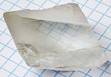
A
calcite crystal laid upon a graph paper with blue lines showing the double refraction

In this example, optic axis along the surface is shown perpendicular to plane of incidence. Incoming light in the
s
polarization (which means perpendicular to plane of incidence - and so
in this example becomes "parallel polarisation" to optic axis, thus is
called extraordinary ray) sees a greater
refractive index than light in the
p polarization (which becomes ordinary ray because "perpendicular polarisation" to optic axis) and so
s polarization ray is undergoing greater
refraction on entering and exiting the crystal.

Doubly
refracted image as seen through a calcite crystal, seen through a
rotating polarizing filter illustrating the opposite polarization states
of the two images.
Sources of optical birefringence
View from under the
Sky Pool, London with coloured fringes due to stress birefringence of partially polarised skylight through a circular polariser
While the best known source of birefringence is the entrance of light into an anisotropic crystal, it can result in otherwise optically isotropic materials in a few ways:
- Stress birefringence
results when a normally isotropic solid is stressed and deformed (i.e.,
stretched or bent) causing a loss of physical isotropy and consequently
a loss of isotropy in the material's permittivity tensor;
- Form birefringence, whereby structure elements such as rods, having
one refractive index, are suspended in a medium with a different
refractive index. When the lattice spacing is much smaller than a
wavelength, such a structure is described as a metamaterial;
- By the Pockels or Kerr effect, whereby an applied electric field induces birefringence due to nonlinear optics;
- By the self or forced alignment into thin films of amphiphilic molecules such as lipids, some surfactants or liquid crystals[citation needed];
- Circular birefringence takes place generally not in materials which are anisotropic but rather ones which are chiral. This can include liquids where there is an enantiomeric excess of a chiral molecule, that is, one that has stereo isomers;
- By the Faraday effect, where a longitudinal magnetic field causes some materials to become circularly birefringent (having slightly different indices of refraction for left- and right-handed circular polarizations), similar to optical activity while the field is applied.
Sandwiched in between crossed polarizers, clear polystyrene cutlery exhibits wavelength-dependent birefringence

Reflective twisted-nematic
liquid-crystal display. Light reflected by the surface (6) (or coming from a
backlight)
is horizontally polarized (5) and passes through the liquid-crystal
modulator (3) sandwiched in between transparent layers (2, 4) containing
electrodes. Horizontally polarized light is blocked by the vertically
oriented polarizer (1), except where its polarization has been rotated
by the liquid crystal (3), appearing bright to the viewer.
Measurement
Birefringence and other polarization-based optical effects (such as optical rotation and linear or circular dichroism)
can be observed by measuring any change in the polarization of light
passing through the material. These measurements are known as polarimetry.
Polarized light microscopes, which contain two polarizers that are at
90° to each other on either side of the sample, are used to visualize
birefringence, since light that has not been affected by
birefringence remains in a polarization that is totally rejected by the
second polarizer ("analyzer"). The addition of quarter-wave plates
permits examination using circularly polarized light. Determination of
the change in polarization state using such an apparatus is the basis of
ellipsometry, by which the optical properties of specular surfaces can be gauged through reflection.
Birefringence measurements have been made with phase-modulated systems for examining the transient flow behaviour of fluids.[13][14] Birefringence of lipid bilayers can be measured using dual-polarization interferometry.
This provides a measure of the degree of order within these fluid
layers and how this order is disrupted when the layer interacts with
other biomolecules.
For the 3D measurement of birefringence, a technique based on holographic tomography [1] can be used.
https://en.wikipedia.org/wiki/Birefringence
Photoelasticity describes changes in the optical properties of a material under mechanical deformation. It is a property of all dielectric media and is often used to experimentally determine the stress distribution in a material, where it gives a picture of stress distributions around discontinuities in materials. Photoelastic experiments (also informally referred to as photoelasticity)
are an important tool for determining critical stress points in a
material, and are used for determining stress concentration in irregular
geometries.
https://en.wikipedia.org/wiki/Photoelasticity
The optical properties of a material define how it interacts with light. The optical properties of matter are studied in optical physics, a subfield of optics. The optical properties of matter include:
A basic distinction is between isotropic materials, which exhibit the same properties regardless of the direction of the light, and anisotropic ones, which exhibit different properties when light passes through them in different directions.
The optical properties of matter can lead to a variety of interesting optical phenomena.
Properties of specific materials
https://en.wikipedia.org/wiki/Optical_properties
In optics, optical bistability is an attribute of certain optical devices where two resonant transmissions states are possible and stable, dependent on the input. Optical devices with a feedback mechanism, e.g. a laser, provide two methods of achieving bistability.
- Absorptive bistability utilizes an absorber to block light
inversely dependent on the intensity of the source light. The first
bistable state resides at a given intensity where no absorber is used.
The second state resides at the point where the light intensity
overcomes the absorber's ability to block light.
- Refractive bistability utilizes an optical mechanism that changes its refractive index
inversely dependent on the intensity of the source light. The first
bistable state resides at a given intensity where no optical mechanism
is used. The second state resides at the point where a certain light
intensity causes the light to resonate to the corresponding refractive
index.
This effect is caused by two factors
- Nonlinear atom-field interaction
- Feedback effect of mirror
Important cases that might be regarded are:
- Atomic detuning
- Cooperating factor
- Cavity mistuning
Applications of this phenomenon include its use in optical transmitters, memory elements and pulse shapers.
Optical bistability was first observed within vapor of sodium during 1974.[1]
Intrinsic bistability
When the feedback mechanism is provided by an internal procedure (not by an external entity like the mirror within the Interferometers), the latter will be known as intrinsic optical bistability.[2] This process can be seen in nonlinear media containing the nanoparticles through which the effect of surface plasmon resonance can potentially occur.[3]
References
Gibbs, Hyatt (1985). "Introduction to Optical Bistability". Optical Bistability: Controlling Light With Light. Quantum electronics--principles and applications. Orlando, FL: Academic Press Inc. p. 1. ISBN 978-0122819407. Retrieved June 16, 2021.
Goldstone, J. A., and E. Garmire. "Intrinsic optical bistability in nonlinear media". Physical review letters 53.9 (1984): 910. https://doi.org/10.1103/PhysRevLett.53.910
- Sharif,
Morteza A., et al. "Difference Frequency Generation-based ultralow
threshold Optical Bistability in graphene at visible frequencies, an
experimental realization". Journal of Molecular Liquids 284 (2019): 92–101. https://doi.org/10.1016/j.molliq.2019.03.167
Category:
https://en.wikipedia.org/wiki/Optical_bistability
Surface plasmon resonance (SPR) is a phenomenon that
occurs where electrons in a thin metal sheet become excited by light
that is directed to the sheet with a particular angle of incidence, and
then travel parallel to the sheet. Assuming a constant light source
wavelength and that the metal sheet is thin, the angle of incidence that
triggers SPR is related to the refractive index of the material and
even a small change in the refractive index will cause SPR to not be
observed. This makes SPR a possible technique for detecting particular
substances (analytes) and SPR biosensors have been developed to detect various important biomarkers[1]
https://en.wikipedia.org/wiki/Surface_plasmon_resonance
Surface plasmon polaritons (SPPs) are electromagnetic waves that travel along a metal–dielectric or metal–air interface, practically in the infrared or visible-frequency. The term "surface plasmon polariton" explains that the wave involves both charge motion in the metal ("surface plasmon") and electromagnetic waves in the air or dielectric ("polariton").[1]
They are a type of surface wave,
guided along the interface in much the same way that light can be
guided by an optical fiber. SPPs have a shorter wavelength than light in
vacuum at the same frequency (photons).[2] Hence, SPPs can have a higher momentum and local field intensity.[2]
Perpendicular to the interface, they have subwavelength-scale
confinement. An SPP will propagate along the interface until its energy
is lost either to absorption in the metal or scattering into other
directions (such as into free space).
Application of SPPs enables subwavelength optics in microscopy and photolithography beyond the diffraction limit.
It also enables the first steady-state micro-mechanical measurement of a
fundamental property of light itself: the momentum of a photon in a
dielectric medium. Other applications are photonic data storage, light generation, and bio-photonics.[3][2][4][5][6]
https://en.wikipedia.org/wiki/Surface_plasmon_polariton
A superlens, or super lens, is a lens which uses metamaterials to go beyond the diffraction limit. The diffraction limit is a feature of conventional lenses and microscopes
that limits the fineness of their resolution depending on the
illumination wavelength and the numerical aperture NA of the objective
lens. Many lens designs have been proposed that go beyond the
diffraction limit in some way, but constraints and obstacles face each
of them.[1]
History
In 1873 Ernst Abbe
reported that conventional lenses are incapable of capturing some fine
details of any given image. The superlens is intended to capture such
details. The limitation of conventional lenses has inhibited progress in the biological sciences. This is because a virus or DNA molecule cannot be resolved with the highest powered conventional microscopes. This limitation extends to the minute processes of cellular proteins moving alongside microtubules of a living cell in their natural environments. Additionally, computer chips and the interrelated microelectronics continue to be manufactured to smaller and smaller scales. This requires specialized optical equipment,
which is also limited because these use conventional lenses. Hence,
the principles governing a superlens show that it has potential for
imaging DNA molecules, cellular protein processes, and aiding in the manufacture of even smaller computer chips and microelectronics.[2][3][4][5]
Furthermore, conventional lenses capture only the propagating light waves.
These are waves that travel from a light source or an object to a lens,
or the human eye. This can alternatively be studied as the far field. In contrast, a superlens captures propagating light waves and waves that stay on top of the surface of an object, which, alternatively, can be studied as both the far field and the near field.[6][7]
In the early 20th century the term "superlens" was used by Dennis Gabor to describe something quite different: a compound lenslet array system.[8]
Theory
Image formation
Schematic
depictions and images of commonly used metallic nanoprobes that can be
used to see a sample in nanometer resolution. Notice that the tips of
the three nanoprobes are 100 nanometers.
[4]An image of an object can be defined as a tangible or visible
representation of the features of that object. A requirement for image
formation is interaction with fields of electromagnetic radiation. Furthermore, the level of feature detail, or image resolution, is limited to a length of a wave of radiation. For example, with optical microscopy, image production and resolution depends on the length of a wave of visible light. However, with a superlens, this limitation may be removed, and a new class of image generated.[9]
Electron beam lithography can overcome this resolution limit. Optical microscopy, on the other hand cannot, being limited to some value just above 200 nanometers.[4] However, new technologies combined with optical microscopy are beginning to allow increased feature resolution (see sections below).
One definition of being constrained by the resolution barrier, is a resolution cut off at half the wavelength of light. The visible spectrum has a range that extends from 390 nanometers to 750 nanometers. Green light, half way in between, is around 500 nanometers. Microscopy takes into account parameters such as lens aperture, distance from the object to the lens, and the refractive index of the observed material. This combination defines the resolution cutoff, or microscopy optical limit, which tabulates to 200 nanometers. Therefore, conventional lenses,
which literally construct an image of an object by using "ordinary"
light waves, discard information that produces very fine, and minuscule
details of the object that are contained in evanescent waves. These dimensions are less than 200 nanometers. For this reason, conventional optical systems, such as microscopes, have been unable to accurately image very small, nanometer-sized structures or nanometer-sized organisms in vivo, such as individual viruses, or DNA molecules.[4][5]
The limitations of standard optical microscopy (bright-field microscopy) lie in three areas:
Live biological cells
in particular generally lack sufficient contrast to be studied
successfully, because the internal structures of the cell are mostly
colorless and transparent. The most common way to increase contrast is
to stain the different structures with selective dyes, but often this involves killing and fixing the sample. Staining may also introduce artifacts,
apparent structural details that are caused by the processing of the
specimen and are thus not a legitimate feature of the specimen.
Conventional lens
The conventional glass lens is pervasive throughout our society and in the sciences. It is one of the fundamental tools of optics simply because it interacts with various wavelengths of light. At the same time, the wavelength of light can be analogous to the width of a pencil used to draw the ordinary images. The limit intrudes in all kinds of ways. For example, the laser used in a digital video system cannot read details from a DVD that are smaller than the wavelength of the laser. This limits the storage capacity of DVDs.[10]
Thus, when an object emits or reflects light there are two types of electromagnetic radiation associated with this phenomenon. These are the near field radiation and the far field
radiation. As implied by its description, the far field escapes beyond
the object. It is then easily captured and manipulated by a conventional
glass lens. However, useful (nanometer-sized) resolution details are
not observed, because they are hidden in the near field. They remain
localized, staying much closer to the light emitting object, unable to
travel, and unable to be captured by the conventional lens. Controlling
the near field radiation, for high resolution, can be accomplished with a
new class of materials not easily obtained in nature. These are unlike
familiar solids, such as crystals, which derive their properties from atomic and molecular units. The new material class, termed metamaterials,
obtains its properties from its artificially larger structure. This
has resulted in novel properties, and novel responses, which allow for details of images that surpass the limitations imposed by the wavelength of light.[10]
Subwavelength imaging
The
"Electrocomposeur" was an electron-beam lithography machine (electron
microscope) designed for mask writing. It was developed in the early
1970s and deployed in the mid 1970s.
This has led to the desire to view live biological cell interactions in a real time, natural environment, and the need for subwavelength imaging. Subwavelength imaging can be defined as optical microscopy
with the ability to see details of an object or organism below the
wavelength of visible light (see discussion in the above sections). In
other words, to have the capability to observe, in real time, below 200
nanometers. Optical microscopy is a non-invasive technique and
technology because everyday light is the transmission medium. Imaging below the optical limit in optical microscopy (subwavelength) can be engineered for the cellular level, and nanometer level in principle.
For example, in 2007 a technique was demonstrated where a metamaterials-based lens coupled with a conventional optical lens could manipulate visible light to see (nanoscale) patterns that were too small to be observed with an ordinary optical microscope. This has potential applications not only for observing a whole living cell, or for observing cellular processes, such as how proteins and fats move in and out of cells. In the technology domain, it could be used to improve the first steps of photolithography and nanolithography, essential for manufacturing ever smaller computer chips.[4][11]
Focusing at subwavelength has become a unique imaging technique which allows visualization of features on the viewed object which are smaller than the wavelength of the photons
in use. A photon is the minimum unit of light. While previously thought
to be physically impossible, subwavelength imaging has been made
possible through the development of metamaterials. This is generally accomplished using a layer of metal such as gold or silver a few atoms thick, which acts as a superlens, or by means of 1D and 2D photonic crystals.[12][13]
There is a subtle interplay between propagating waves, evanescent
waves, near field imaging and far field imaging discussed in the
sections below.[4][14]
Early subwavelength imaging
Metamaterial lenses (Superlenses) are able to reconstruct nanometer sized images by producing a negative refractive index in each instance. This compensates for the swiftly decaying evanescent waves. Prior to metamaterials, numerous other techniques had been proposed and even demonstrated for creating super-resolution microscopy. As far back as 1928, Irish physicist Edward Hutchinson Synge, is given credit for conceiving and developing the idea for what would ultimately become near-field scanning optical microscopy.[15][16][17]
In 1974 proposals for two-dimensional fabrication techniques were presented. These proposals included contact imaging to create a pattern in relief, photolithography, electron lithography, X-ray lithography, or ion bombardment, on an appropriate planar substrate.[18] The shared technological goals of the metamaterial lens and the variety of lithography aim to optically resolve features having dimensions much smaller than that of the vacuum wavelength of the exposing light.[19][20] In 1981 two different techniques of contact imaging of planar (flat) submicroscopic metal patterns with blue light (400 nm) were demonstrated. One demonstration resulted in an image resolution of 100 nm and the other a resolution of 50 to 70 nm.[20]
In 1995, John Guerra
combined a transparent grating having 50 nm lines and spaces (the
"metamaterial") with a conventional microscope immersion objective. The
resulting "superlens" resolved a silicon sample also having 50 nm lines
and spaces, far beyond the classical diffraction limit imposed by the
illumination having 650 nm wavelength in air.[21]
Since at least 1998 near field optical lithography
was designed to create nanometer-scale features. Research on this
technology continued as the first experimentally demonstrated negative index metamaterial came into existence in 2000–2001. The effectiveness of electron-beam lithography was also being researched at the beginning of the new millennium for nanometer-scale applications. Imprint lithography was shown to have desirable advantages for nanometer-scaled research and technology.[19][22]
Advanced deep UV photolithography can now offer sub-100 nm resolution, yet the minimum feature size and spacing between patterns are determined by the diffraction limit of light. Its derivative technologies such as evanescent near-field
lithography, near-field interference lithography, and phase-shifting
mask lithography were developed to overcome the diffraction limit.[19]
In the year 2000, John Pendry proposed using a metamaterial lens to achieve nanometer-scaled imaging for focusing below the wavelength of light.[1][23]
Analysis of the diffraction limit
The
original problem of the perfect lens: The general expansion of an EM
field emanating from a source consists of both propagating waves and
near-field or evanescent waves. An example of a 2-D line source with an
electric field which has S-polarization will have plane waves consisting
of propagating and evanescent components, which advance parallel to the
interface.[24]
As both the propagating and the smaller evanescent waves advance in a
direction parallel to the medium interface, evanescent waves decay in
the direction of propagation. Ordinary (positive index) optical elements
can refocus the propagating components, but the exponentially decaying
inhomogeneous components are always lost, leading to the diffraction
limit for focusing to an image.[24]
A superlens is a lens which is capable of subwavelength imaging, allowing for magnification of near field rays. Conventional lenses have a resolution on the order of one wavelength
due to the so-called diffraction limit. This limit hinders imaging very
small objects, such as individual atoms, which are much smaller than
the wavelength of visible light. A superlens is able to beat the
diffraction limit. An example is the initial lens described by Pendry,
which uses a slab of material with a negative index of refraction as a flat lens. In theory, a perfect lens would be capable of perfect focus – meaning that it could perfectly reproduce the electromagnetic field of the source plane at the image plane.
The diffraction limit as restriction on resolution
The
performance limitation of conventional lenses is due to the diffraction
limit. Following Pendry (2000), the diffraction limit can be understood
as follows. Consider an object and a lens placed along the z-axis so
the rays from the object are traveling in the +z direction. The field
emanating from the object can be written in terms of its angular spectrum method, as a superposition of plane waves:

where  is a function of
  :
:

Only the positive square root is taken as the energy is going in the +z direction. All of the components of the angular spectrum of the image for which is real are transmitted and re-focused by an ordinary lens. However, if

then becomes imaginary, and the wave is an evanescent wave, whose amplitude decays as the wave propagates along the z axis. This results in the loss of the high-angular-frequency
components of the wave, which contain information about the
high-frequency (small-scale) features of the object being imaged. The
highest resolution that can be obtained can be expressed in terms of the
wavelength:


A superlens overcomes the limit. A Pendry-type superlens has an index of n=−1 (ε=−1, µ=−1), and in such a material, transport of energy in the +z direction requires the z component of the wave vector to have opposite sign:

For large angular frequencies, the evanescent wave now grows,
so with proper lens thickness, all components of the angular spectrum
can be transmitted through the lens undistorted. There are no problems
with conservation of energy, as evanescent waves carry none in the direction of growth: the Poynting vector
is oriented perpendicularly to the direction of growth. For traveling
waves inside a perfect lens, the Poynting vector points in direction
opposite to the phase velocity.[3]
Effects of negative index of refraction
a)
When a wave strikes a positive refraction index material from a vacuum.
b) When a wave strikes a negative-refraction-index material from a
vacuum. c) When an object is placed in front of an object with n=−1, light from it is refracted so it focuses once inside the lens and once outside. This allows subwavelength imaging.
Normally, when a wave passes through the interface of two materials, the wave appears on the opposite side of the normal. However, if the interface is between a material with a positive index of refraction and another material with a negative index of refraction, the wave will appear on the same side of the normal. Pendry's idea of a perfect lens is a flat material where n=−1.
Such a lens allows near-field rays, which normally decay due to the
diffraction limit, to focus once within the lens and once outside the
lens, allowing subwavelength imaging.[25]
Development and construction
Superlens construction was at one time thought to be impossible. In 2000, Pendry claimed that a simple slab of left-handed material would do the job.[26]
The experimental realization of such a lens took, however, some more
time, because it is not that easy to fabricate metamaterials with both
negative permittivity and permeability. Indeed, no such material exists naturally and construction of the required metamaterials
is non-trivial. Furthermore, it was shown that the parameters of the
material are extremely sensitive (the index must equal −1); small
deviations make the subwavelength resolution unobservable.[27][28]
Due to the resonant nature of metamaterials, on which many (proposed)
implementations of superlenses depend, metamaterials are highly
dispersive. The sensitive nature of the superlens to the material
parameters causes superlenses based on metamaterials to have a limited
usable frequency range. This initial theoretical superlens design
consisted of a metamaterial that compensated for wave decay and reconstructs images in the near field. Both propagating and evanescent waves could contribute to the resolution of the image.[1][23][29]
Pendry also suggested that a lens having only one negative
parameter would form an approximate superlens, provided that the
distances involved are also very small and provided that the source
polarization is appropriate. For visible light this is a useful
substitute, since engineering metamaterials with a negative permeability
at the frequency of visible light is difficult. Metals are then a good
alternative as they have negative permittivity (but not negative
permeability). Pendry suggested using silver
due to its relatively low loss at the predicted wavelength of operation
(356 nm). In 2003 Pendry's theory was first experimentally demonstrated[13]
at RF/microwave frequencies. In 2005, two independent groups verified
Pendry's lens at UV range, both using thin layers of silver illuminated
with UV light to produce "photographs" of objects smaller than the
wavelength.[30][31] Negative refraction of visible light was experimentally verified in an yttrium orthovanadate (YVO4) bicrystal in 2003.[32]
It was discovered that a simple superlens design for microwaves could use an array of parallel conducting wires.
[33] This structure was shown to be able to improve the resolution of MRI imaging.
In 2004, the first superlens with a negative refractive index provided resolution three times better than the diffraction limit and was demonstrated at microwave frequencies.[34] In 2005, the first near field superlens was demonstrated by N.Fang et al., but the lens did not rely on negative refraction. Instead, a thin silver film was used to enhance the evanescent modes through surface plasmon coupling.[35][36] Almost at the same time Melville and Blaikie succeeded with a near field superlens. Other groups followed.[30][37] Two developments in superlens research were reported in 2008.[38]
In the second case, a metamaterial was formed from silver nanowires
which were electrochemically deposited in porous aluminium oxide. The
material exhibited negative refraction.[39]
The imaging performance of such isotropic negative dielectric constant
slab lenses were also analyzed with respect to the slab material and
thickness.[40]
Subwavelength imaging opportunities with planar uniaxial anisotropic
lenses, where the dielectric tensor components are of the opposite sign,
have also been studied as a function of the structure parameters.[41]
The superlens has not yet been demonstrated at visible or near-infrared
frequencies (Nielsen, R. B.; 2010). Furthermore, as dispersive
materials, these are limited to functioning at a single wavelength.
Proposed solutions are metal–dielectric composites (MDCs)[42] and multilayer lens structures.[43]
The multi-layer superlens appears to have better subwavelength
resolution than the single layer superlens. Losses are less of a concern
with the multi-layer system, but so far it appears to be impractical
because of impedance mis-match.[35]
While the evolution of nanofabrication techniques continues to
push the limits in fabrication of nanostructures, surface roughness
remains an inevitable source of concern in the design of nano-photonic
devices. The impact of this surface roughness on the effective
dielectric constants and subwavelength image resolution of multilayer
metal–insulator stack lenses has also been studied.
[44]
Perfect lenses
When the world is observed through conventional lenses, the sharpness of the image is determined by and limited to the wavelength of light. Around the year 2000, a slab of negative index metamaterial was theorized to create a lens with capabilities beyond conventional (positive index) lenses. Pendry proposed that a thin slab of negative refractive metamaterial might overcome known problems with common lenses to achieve a "perfect" lens that would focus the entire spectrum, both the propagating as well as the evanescent spectra.[1][45]
A slab of silver was proposed as the metamaterial. More specifically, such silver thin film can be regarded as a metasurface. As light moves away (propagates) from the source, it acquires an arbitrary phase. Through a conventional lens the phase remains consistent, but the evanescent waves decay exponentially. In the flat metamaterial DNG slab, normally decaying evanescent waves are contrarily amplified. Furthermore, as the evanescent waves are now amplified, the phase is reversed.[1]
Therefore, a type of lens was proposed, consisting of a metal film metamaterial. When illuminated near its plasma frequency, the lens could be used for superresolution imaging that compensates for wave decay and reconstructs images in the near-field. In addition, both propagating and evanescent waves contribute to the resolution of the image.[1]
Pendry suggested that left-handed slabs allow "perfect imaging" if they are completely lossless, impedance matched, and their refractive index
is −1 relative to the surrounding medium. Theoretically, this would be a
breakthrough in that the optical version resolves objects as minuscule
as nanometers across. Pendry predicted that Double negative metamaterials (DNG) with a refractive index of n=−1,
can act, at least in principle, as a "perfect lens" allowing imaging
resolution which is limited not by the wavelength, but rather by
material quality.[1][46][47][48]
Other studies concerning the perfect lens
Further research demonstrated that Pendry's theory behind the perfect lens was not exactly correct. The analysis of the focusing of the evanescent spectrum (equations 13–21 in reference[1])
was flawed. In addition, this applies to only one (theoretical)
instance, and that is one particular medium that is lossless,
nondispersive and the constituent parameters are defined as:[45]
- ε(ω) / ε0=µ(ω) / µ0=−1, which in turn results in a negative refraction of n=−1
However, the final intuitive result of this theory that both the propagating and evanescent waves are focused, resulting in a converging focal point within the slab and another convergence (focal point) beyond the slab turned out to be correct.[45]
If the DNG metamaterial medium has a large negative index or becomes lossy or dispersive, Pendry's perfect lens effect cannot be realized. As a result, the perfect lens effect does not exist in general. According to FDTD simulations
at the time (2001), the DNG slab acts like a converter from a pulsed
cylindrical wave to a pulsed beam. Furthermore, in reality (in
practice), a DNG medium must be and is dispersive and lossy, which can
have either desirable or undesirable effects, depending on the research
or application. Consequently, Pendry's perfect lens effect is
inaccessible with any metamaterial designed to be a DNG medium.[45]
Another analysis, in 2002,[24] of the perfect lens concept
showed it to be in error while using the lossless, dispersionless DNG
as the subject. This analysis mathematically demonstrated that
subtleties of evanescent waves, restriction to a finite
slab and absorption had led to inconsistencies and divergencies that
contradict the basic mathematical properties of scattered wave fields.
For example, this analysis stated that absorption, which is linked to dispersion, is always present in practice, and absorption tends to transform amplified waves into decaying ones inside this medium (DNG).[24]
A third analysis of Pendry's perfect lens concept, published in 2003,[49] used the recent demonstration of negative refraction at microwave frequencies[50] as confirming the viability of the fundamental concept of the perfect lens. In addition, this demonstration was thought to be experimental evidence that a planar DNG metamaterial would refocus the far field radiation of a point source. However, the perfect lens would require significantly different values for permittivity, permeability, and spatial periodicity than the demonstrated negative refractive sample.[49][50]
This study agrees that any deviation from conditions where ε=µ=−1
results in the normal, conventional, imperfect image that degrades
exponentially i.e., the diffraction limit. The perfect lens solution in
the absence of losses is again, not practical, and can lead to
paradoxical interpretations.[24]
It was determined that although resonant surface plasmons
are undesirable for imaging, these turn out to be essential for
recovery of decaying evanescent waves. This analysis discovered that metamaterial periodicity has a significant effect on the recovery of types of evanescent components. In addition, achieving subwavelength resolution is possible with current technologies. Negative refractive indices
have been demonstrated in structured metamaterials. Such materials can
be engineered to have tunable material parameters, and so achieve the
optimal conditions. Losses up to microwave frequencies can be minimized in structures utilizing superconducting
elements. Furthermore, consideration of alternate structures may lead
to configurations of left-handed materials that can achieve
subwavelength focusing. Such structures were being studied at the time.[24]
An effective approach for the compensation of losses in
metamaterials, called plasmon injection scheme, has been recently
proposed.[51]
The plasmon injection scheme has been applied theoretically to
imperfect negative index flat lenses with reasonable material losses and
in the presence of noise[52][53] as well as hyperlenses.[54]
It has been shown that even imperfect negative index flat lenses
assisted with plasmon injection scheme can enable subdiffraction imaging
of objects which is otherwise not possible due to the losses and noise.
Although plasmon injection scheme was originally conceptualized for
plasmonic metamaterials,[51]
the concept is general and applicable to all types electromagnetic
modes. The main idea of the scheme is the coherent superposition of the
lossy modes in the metamaterial with an appropriately structured
external auxiliary field. This auxiliary field accounts for the losses
in the metamaterial, hence effectively reduces the losses experienced by
the signal beam or object field in the case of a metamaterial lens. The
plasmon injection scheme can be implemented either physically[53] or equivalently through deconvolution post-processing method.[52][54]
However, the physical implementation has shown to be more effective
than the deconvolution. Physical construction of convolution and
selective amplification of the spatial frequencies within a narrow
bandwidth are the keys to the physical implementation of the plasmon
injection scheme. This loss compensation scheme is ideally suited
especially for metamaterial lenses since it does not require gain
medium, nonlinearity, or any interaction with phonons. Experimental
demonstration of the plasmon injection scheme has not yet been shown
partly because the theory is rather new.
Near-field imaging with magnetic wires
A prism composed of high performance
Swiss rolls which behaves as a magnetic faceplate, transferring a magnetic field distribution faithfully from the input to the output face.
[55]Pendry's theoretical lens was designed to focus both propagating waves and the near-field evanescent waves. From permittivity "ε" and magnetic permeability
"µ" an index of refraction "n" is derived. The index of refraction
determines how light is bent on traversing from one material to another.
In 2003, it was suggested that a metamaterial constructed with
alternating, parallel, layers of n=−1 materials and n=+1 materials, would be a more effective design for a metamaterial lens. It is an effective medium made up of a multi-layer stack, which exhibits birefringence, n2=∞, nx=0. The effective refractive indices are then perpendicular and parallel, respectively.[55]
Like a conventional lens, the z-direction is along the axis of the roll. The resonant frequency (w0)
– close to 21.3 MHz – is determined by the construction of the roll.
Damping is achieved by the inherent resistance of the layers and the
lossy part of permittivity.[55]
Simply put, as the field pattern is transferred from the input to
the output face of a slab, so the image information is transported
across each layer. This was experimentally demonstrated. To test the
two-dimensional imaging performance of the material, an antenna was
constructed from a pair of anti-parallel wires in the shape of the
letter M. This generated a line of magnetic flux, so providing a
characteristic field pattern for imaging. It was placed horizontally,
and the material, consisting of 271 Swiss rolls
tuned to 21.5 MHz, was positioned on top of it. The material does
indeed act as an image transfer device for the magnetic field. The shape
of the antenna is faithfully reproduced in the output plane, both in
the distribution of the peak intensity, and in the “valleys” that bound
the M.[55]
A consistent characteristic of the very near (evanescent) field is that the electric and magnetic fields are largely decoupled. This allows for nearly independent manipulation of the electric field with the permittivity and the magnetic field with the permeability.[55]
Furthermore, this is highly anisotropic system.
Therefore, the transverse (perpendicular) components of the EM field
which radiate the material, that is the wavevector components kx and ky, are decoupled from the longitudinal component kz.
So, the field pattern should be transferred from the input to the
output face of a slab of material without degradation of the image
information.[55]
Optical superlens with silver metamaterial
In 2003, a group of researchers showed that optical evanescent waves would be enhanced as they passed through a silver metamaterial lens. This was referred to as a diffraction-free lens. Although a coherent, high-resolution, image was not intended, nor achieved, regeneration of the evanescent field was experimentally demonstrated.[56][57]
By 2003 it was known for decades that evanescent waves could be enhanced by producing excited states at the interface surfaces. However, the use of surface plasmons to reconstruct evanescent components was not tried until Pendry's recent proposal (see "Perfect lens" above). By studying films of varying thickness it has been noted that a rapidly growing transmission coefficient
occurs, under the appropriate conditions. This demonstration provided
direct evidence that the foundation of superlensing is solid, and
suggested the path that will enable the observation of superlensing at
optical wavelengths.[57]
In 2005, a coherent, high-resolution, image was produced (based on the 2003 results). A thinner slab of silver (35 nm) was better for sub–diffraction-limited imaging,
which results in one-sixth of the illumination wavelength. This type of
lens was used to compensate for wave decay and reconstruct images in
the near-field. Prior attempts to create a working superlens used a slab of silver that was too thick.[23][46]
Objects were imaged as small as 40 nm across. In 2005 the imaging resolution limit for optical microscopes was at about one tenth the diameter of a red blood cell. With the silver superlens this results in a resolution of one hundredth of the diameter of a red blood cell.[56]
Conventional lenses, whether man-made or natural, create images
by capturing the propagating light waves all objects emit and then
bending them. The angle of the bend is determined by the index of
refraction and has always been positive until the fabrication of
artificial negative index materials. Objects also emit evanescent waves
that carry details of the object, but are unobtainable with conventional
optics. Such evanescent waves decay exponentially and thus never become
part of the image resolution, an optics threshold known as the
diffraction limit. Breaking this diffraction limit, and capturing
evanescent waves are critical to the creation of a 100-percent perfect
representation of an object.[23]
In addition, conventional optical materials suffer a diffraction limit because only the propagating components are transmitted (by the optical material) from a light source.[23] The non-propagating components, the evanescent waves, are not transmitted.[24] Moreover, lenses that improve image resolution by increasing the index of refraction are limited by the availability of high-index materials, and point by point subwavelength imaging of electron microscopy
also has limitations when compared to the potential of a working
superlens. Scanning electron and atomic force microscopes are now used
to capture detail down to a few nanometers. However, such microscopes
create images by scanning objects point by point, which means they are
typically limited to non-living samples, and image capture times can
take up to several minutes.[23]
With current optical microscopes, scientists can only make out
relatively large structures within a cell, such as its nucleus and
mitochondria. With a superlens, optical microscopes could one day reveal
the movements of individual proteins traveling along the microtubules
that make up a cell's skeleton, the researchers said. Optical
microscopes can capture an entire frame with a single snapshot in a
fraction of a second. With superlenses this opens up nanoscale imaging
to living materials, which can help biologists better understand cell
structure and function in real time.[23]
Advances of magnetic coupling in the THz and infrared
regime provided the realization of a possible metamaterial superlens.
However, in the near field, the electric and magnetic responses of
materials are decoupled. Therefore, for transverse magnetic (TM) waves,
only the permittivity needed to be considered. Noble metals, then become
natural selections for superlensing because negative permittivity is
easily achieved.[23]
By designing the thin metal slab so that the surface current oscillations (the surface plasmons)
match the evanescent waves from the object, the superlens is able to
substantially enhance the amplitude of the field. Superlensing results
from the enhancement of evanescent waves by surface plasmons.[23][56]
The key to the superlens is its ability to significantly enhance
and recover the evanescent waves that carry information at very small
scales. This enables imaging well below the diffraction limit. No lens
is yet able to completely reconstitute all the evanescent waves emitted
by an object, so the goal of a 100-percent perfect image will persist.
However, many scientists believe that a true perfect lens is not
possible because there will always be some energy absorption loss as the
waves pass through any known material. In comparison, the superlens
image is substantially better than the one created without the silver
superlens.[23]
50-nm flat silver layer
In February 2004, an electromagnetic radiation focusing system, based on a negative index metamaterial plate, accomplished subwavelength imaging in the microwave domain. This showed that obtaining separated images at much less than the wavelength of light is possible.[58] Also, in 2004, a silver layer was used for sub-micrometre
near-field imaging. Super high resolution was not achieved, but this
was intended. The silver layer was too thick to allow significant
enhancements of evanescent field components.[30]
In early 2005, feature resolution was achieved with a different
silver layer. Though this was not an actual image, it was intended.
Dense feature resolution down to 250 nm was produced in a 50 nm thick photoresist using illumination from a mercury lamp. Using simulations (FDTD),
the study noted that resolution improvements could be expected for
imaging through silver lenses, rather than another method of near field
imaging.[59]
Building on this prior research, super resolution was achieved at optical frequencies using a 50 nm flat silver layer. The capability of resolving an image beyond the diffraction limit, for far-field imaging, is defined here as superresolution.[30]
The image fidelity is much improved over earlier results of the
previous experimental lens stack. Imaging of sub-micrometre features has
been greatly improved by using thinner silver and spacer layers, and by
reducing the surface roughness of the lens stack. The ability of the
silver lenses to image the gratings has been used as the ultimate
resolution test, as there is a concrete limit for the ability of a
conventional (far field) lens to image a periodic object – in this case
the image is a diffraction grating. For normal-incidence illumination
the minimum spatial period that can be resolved with wavelength λ
through a medium with refractive index n is λ/n. Zero contrast would
therefore be expected in any (conventional) far-field image below this
limit, no matter how good the imaging resist might be.[30]
The (super) lens stack here results in a computational result of a
diffraction-limited resolution of 243 nm. Gratings with periods from
500 nm down to 170 nm are imaged, with the depth of the modulation in
the resist reducing as the grating period reduces. All of the gratings
with periods above the diffraction limit (243 nm) are well resolved.[30]
The key results of this experiment are super-imaging of the
sub-diffraction limit for 200 nm and 170 nm periods. In both cases the
gratings are resolved, even though the contrast is diminished, but this
gives experimental confirmation of Pendry's superlensing proposal.[30]
For further information see Fresnel number and Fresnel diffraction
Negative index GRIN lenses
Gradient
Index (GRIN) – The larger range of material response available in
metamaterials should lead to improved GRIN lens design. In particular,
since the permittivity and permeability of a metamaterial can be
adjusted independently, metamaterial GRIN lenses can presumably be
better matched to free space. The GRIN lens is constructed by using a
slab of NIM with a variable index of refraction in the y direction,
perpendicular to the direction of propagation z.[60]
Far-field superlens
In
2005, a group proposed a theoretical way to overcome the near-field
limitation using a new device termed a far-field superlens (FSL), which
is a properly designed periodically corrugated metallic slab-based
superlens.[61]
Imaging was experimentally demonstrated in the far field, taking
the next step after near-field experiments. The key element is termed as
a far-field superlens (FSL) which consists of a conventional superlens
and a nanoscale coupler.[62]
Focusing beyond the diffraction limit with far-field time reversal
An
approach is presented for subwavelength focusing of microwaves using
both a time-reversal mirror placed in the far field and a random
distribution of scatterers placed in the near field of the focusing
point.[63]
Hyperlens
Once
capability for near-field imaging was demonstrated, the next step was
to project a near-field image into the far-field. This concept,
including technique and materials, is dubbed "hyperlens".[64][65]
In May 2012, calculations showed an ultraviolet (1200-1400 THz) hyperlens can be created using alternating layers of boron nitride and graphene.[66]
In February 2018, a mid-infrared (~5-25μm) hyperlens was introduced, made from a variably doped indium arsenide multilayer, which offered drastically lower losses.[67]
The capability of a metamaterial-hyperlens for sub-diffraction-limited imaging is shown below.
Sub-diffraction imaging in the far field
With conventional optical lenses, the far field is a limit that is too distant for evanescent waves to arrive intact. When imaging an object, this limits the optical resolution of lenses to the order of the wavelength of light. These non-propagating waves carry detailed information in the form of high spatial resolution, and overcome limitations. Therefore, projecting image details, normally limited by diffraction into the far field does require recovery of the evanescent waves.[68]
In essence steps leading up to this investigation and demonstration was the employment of an anisotropic metamaterial with a hyperbolic dispersion. The effect was such that ordinary evanescent waves propagate along the radial direction of the layered metamaterial. On a microscopic level the large spatial frequency waves propagate through coupled surface plasmon excitations between the metallic layers.[68]
In 2007, just such an anisotropic metamaterial was employed as a magnifying optical hyperlens. The hyperlens consisted of a curved periodic stack of thin silver and alumina
(at 35 nanometers thick) deposited on a half-cylindrical cavity, and
fabricated on a quartz substrate. The radial and tangential permittivities have different signs.[68]
Upon illumination, the scattered evanescent field
from the object enters the anisotropic medium and propagates along the
radial direction. Combined with another effect of the metamaterial, a
magnified image at the outer diffraction limit-boundary of the hyperlens
occurs. Once the magnified feature is larger than (beyond) the
diffraction limit, it can then be imaged with a conventional optical microscope, thus demonstrating magnification and projection of a sub-diffraction-limited image into the far field.[68]
The hyperlens magnifies the object by transforming the scattered evanescent waves into propagating waves in the anisotropic
medium, projecting a spatial resolution high-resolution image into the
far field. This type of metamaterials-based lens, paired with a
conventional optical lens is therefore able to reveal patterns too small
to be discerned with an ordinary optical microscope. In one experiment,
the lens was able to distinguish two 35-nanometer lines etched 150
nanometers apart. Without the metamaterials, the microscope showed only
one thick line.[14]
In a control experiment, the line pair object was imaged without
the hyperlens. The line pair could not be resolved because of the
diffraction limit of the (optical) aperture was limited to 260 nm.
Because the hyperlens supports the propagation of a very broad spectrum
of wave vectors, it can magnify arbitrary objects with
sub-diffraction-limited resolution.[68]
Although this work appears to be limited by being only a cylindrical hyperlens, the next step is to design a spherical
lens. That lens will exhibit three-dimensional capability. Near-field
optical microscopy uses a tip to scan an object. In contrast, this
optical hyperlens magnifies an image that is sub-diffraction-limited.
The magnified sub-diffraction image is then projected into the far
field.[14][68]
The optical hyperlens shows a notable potential for applications,
such as real-time biomolecular imaging and nanolithography. Such a lens
could be used to watch cellular processes that have been impossible to
see. Conversely, it could be used to project an image with extremely
fine features onto a photoresist as a first step in photolithography, a
process used to make computer chips. The hyperlens also has applications
for DVD technology.[14][68]
In 2010, a spherical hyperlens for two dimensional imaging at
visible frequencies was demonstrated experimentally. The spherical
hyperlens was based on silver and titanium oxide in alternating layers
and had strong anisotropic hyperbolic dispersion allowing
super-resolution with visible spectrum. The resolution was 160 nm in the
visible spectrum. It will enable biological imaging at the cellular and
DNA level, with a strong benefit of magnifying sub-diffraction
resolution into far-field.
[69]
Plasmon-assisted microscopy
See Near-field scanning optical microscope.
Super-imaging in the visible frequency range
In 2007 researchers demonstrated super imaging using materials, which create negative refractive index and lensing is achieved in the visible range.[46]
Continual improvements in optical microscopy are needed to keep up with the progress in nanotechnology and microbiology. Advancement in spatial resolution is key. Conventional optical microscopy is limited by a diffraction limit which is on the order of 200 nanometers (wavelength). This means that viruses, proteins, DNA
molecules and many other samples are hard to observe with a regular
(optical) microscope. The lens previously demonstrated with negative refractive index material, a thin planar superlens, does not provide magnification
beyond the diffraction limit of conventional microscopes. Therefore,
images smaller than the conventional diffraction limit will still be
unavailable.[46]
Another approach achieving super-resolution at visible wavelength
is recently developed spherical hyperlens based on silver and titanium
oxide alternating layers. It has strong anisotropic hyperbolic
dispersion allowing super-resolution with converting evanescent waves
into propagating waves. This method is non-fluorescence based
super-resolution imaging, which results in real-time imaging without any
reconstruction of images and information.[69]
Super resolution far-field microscopy techniques
By
2008 the diffraction limit has been surpassed and lateral imaging
resolutions of 20 to 50 nm have been achieved by several
"super-resolution" far-field microscopy techniques, including stimulated
emission depletion (STED) and its related RESOLFT (reversible saturable
optically linear fluorescent transitions) microscopy; saturated
structured illumination microscopy (SSIM) ; stochastic optical
reconstruction microscopy (STORM); photoactivated localization
microscopy (PALM); and other methods using similar principles.[70]
Cylindrical superlens via coordinate transformation
This
began with a proposal by Pendry, in 2003. Magnifying the image required
a new design concept in which the surface of the negatively refracting
lens is curved. One cylinder touches another cylinder, resulting in a
curved cylindrical lens which reproduced the contents of the smaller
cylinder in magnified but undistorted form outside the larger cylinder.
Coordinate transformations are required to curve the original perfect
lens into the cylindrical, lens structure.[71]
This was followed by a 36-page conceptual and mathematical proof in 2005, that the cylindrical superlens works in the quasistatic regime. The debate over the perfect lens is discussed first.[72]
In 2007, a superlens utilizing coordinate transformation was
again the subject. However, in addition to image transfer other useful
operations were discussed; translation, rotation, mirroring and
inversion as well as the superlens effect. Furthermore, elements that
perform magnification are described, which are free from geometric
aberrations, on both the input and output sides while utilizing free
space sourcing (rather than waveguide). These magnifying elements also
operate in the near and far field, transferring the image from near
field to far field.[73]
The cylindrical magnifying superlens was experimentally demonstrated in 2007 by two groups, Liu et al.[68] and Smolyaninov et al.[46][74]
Nano-optics with metamaterials
Nanohole array as a lens
Work in 2007 demonstrated that a quasi-periodic array of nanoholes, in a metal screen, were able to focus the optical energy of a plane wave to form subwavelength spots (hot spots). The distances for the spots was a few tens of wavelengths on the other side of the array, or, in other words, opposite the side of the incident plane wave. The quasi-periodic array of nanoholes functioned as a light concentrator.[75]
In June 2008, this was followed by the demonstrated capability of an array of quasi-crystal nanoholes in a metal screen. More than concentrating hot spots, an image of the point source
is displayed a few tens of wavelengths from the array, on the other
side of the array (the image plane). Also this type of array exhibited a
1 to 1 linear displacement, – from the location of the point source to
its respective, parallel, location on the image plane. In other words,
from x to x + δx. For example, other point sources were similarly
displaced from x' to x' + δx', from x^ to x^ + δx^, and from x^^ to x^^ +
δx^^, and so on. Instead of functioning as a light concentrator, this
performs the function of conventional lens imaging with a 1 to 1 correspondence, albeit with a point source.[75]
However, resolution
of more complicated structures can be achieved as constructions of
multiple point sources. The fine details, and brighter image, that are
normally associated with the high numerical apertures of conventional lenses can be reliably produced. Notable applications for this technology arise when conventional optics is not suitable for the task at hand. For example, this technology is better suited for X-ray imaging, or nano-optical circuits, and so forth.[75]
Nanolens
In 2010, a nano-wire array prototype, described as a three-dimensional (3D) metamaterial-nanolens, consisting of bulk nanowires deposited in a dielectric substrate was fabricated and tested.[76][77]
The metamaterial nanolens was constructed of millions of
nanowires at 20 nanometers in diameter. These were precisely aligned and
a packaged configuration was applied. The lens is able to depict a
clear, high-resolution image of nano-sized objects because it uses both normal propagating EM radiation, and evanescent waves to construct the image. Super-resolution imaging was demonstrated over a distance of 6 times the wavelength
(λ), in the far-field, with a resolution of at least λ/4. This is a
significant improvement over previous research and demonstration of
other near field and far field imaging, including nanohole arrays
discussed below.[76][77]
Light transmission properties of holey metal films
2009-12.
The light transmission properties of holey metal films in the
metamaterial limit, where the unit length of the periodic structures is
much smaller than the operating wavelength, are analyzed theoretically.[78]
Transporting an Image through a subwavelength hole
Theoretically
it appears possible to transport a complex electromagnetic image
through a tiny subwavelength hole with diameter considerably smaller
than the diameter of the image, without losing the subwavelength
details.[79]
Nanoparticle imaging – quantum dots
When
observing the complex processes in a living cell, significant processes
(changes) or details are easy to overlook. This can more easily occur
when watching changes that take a long time to unfold and require
high-spatial-resolution imaging. However, recent research offers a
solution to scrutinize activities that occur over hours or even days
inside cells, potentially solving many of the mysteries associated with
molecular-scale events occurring in these tiny organisms.[80]
A joint research team, working at the National Institute of
Standards and Technology (NIST) and the National Institute of Allergy
and Infectious Diseases (NIAID), has discovered a method of using
nanoparticles to illuminate the cellular interior to reveal these slow
processes. Nanoparticles, thousands of times smaller than a cell, have a
variety of applications. One type of nanoparticle called a quantum dot
glows when exposed to light. These semiconductor particles can be coated
with organic materials, which are tailored to be attracted to specific
proteins within the part of a cell a scientist wishes to examine.[80]
Notably, quantum dots last longer than many organic dyes and
fluorescent proteins that were previously used to illuminate the
interiors of cells. They also have the advantage of monitoring changes
in cellular processes while most high-resolution techniques like
electron microscopy only provide images of cellular processes frozen at
one moment. Using quantum dots, cellular processes involving the dynamic
motions of proteins, are observable (elucidated).[80]
The research focused primarily on characterizing quantum dot
properties, contrasting them with other imaging techniques. In one
example, quantum dots were designed to target a specific type of human
red blood cell protein that forms part of a network structure in the
cell's inner membrane. When these proteins cluster together in a healthy
cell, the network provides mechanical flexibility to the cell so it can
squeeze through narrow capillaries and other tight spaces. But when the
cell gets infected with the malaria parasite, the structure of the
network protein changes.[80]
Because the clustering mechanism is not well understood, it was
decided to examine it with the quantum dots. If a technique could be
developed to visualize the clustering, then the progress of a malaria
infection could be understood, which has several distinct developmental
stages.[80]
Research efforts revealed that as the membrane proteins bunch up,
the quantum dots attached to them are induced to cluster themselves and
glow more brightly, permitting real time observation as the clustering
of proteins progresses. More broadly, the research discovered that when
quantum dots attach themselves to other nanomaterials, the dots' optical
properties change in unique ways in each case. Furthermore, evidence
was discovered that quantum dot optical properties are altered as the
nanoscale environment changes, offering greater possibility of using
quantum dots to sense the local biochemical environment inside cells.[80]
Some concerns remain over toxicity and other properties.
However, the overall findings indicate that quantum dots could be a
valuable tool to investigate dynamic cellular processes.[80]
The abstract from the related published research paper states (in
part): Results are presented regarding the dynamic fluorescence
properties of bioconjugated nanocrystals or quantum dots (QDs) in
different chemical and physical environments. A variety of QD samples
was prepared and compared: isolated individual QDs, QD aggregates, and
QDs conjugated to other nanoscale materials...
See also
|
https://en.wikipedia.org/wiki/Superlens A photonic crystal is an optical nanostructure in which the refractive index changes periodically. This affects the propagation of light in the same way that the structure of natural crystals gives rise to X-ray diffraction and that the atomic lattices (crystal structure) of semiconductors affect their conductivity of electrons. Photonic crystals occur in nature in the form of structural coloration and animal reflectors, and, as artificially produced, promise to be useful in a range of applications.
Photonic crystals can be fabricated for one, two, or three dimensions. One-dimensional photonic crystals can be made of thin film layers deposited on each other. Two-dimensional ones can be made by photolithography,
or by drilling holes in a suitable substrate. Fabrication methods for
three-dimensional ones include drilling under different angles, stacking
multiple 2-D layers on top of each other, direct laser writing, or, for example, instigating self-assembly of spheres in a matrix and dissolving the spheres.
Photonic crystals can, in principle, find uses wherever light must be manipulated. For example, dielectric mirrors
are one-dimensional photonic crystals which can produce ultra-high
reflectivity mirrors at a specified wavelength. Two-dimensional photonic
crystals called photonic-crystal fibers are used for fiber-optic communication, among other applications. Three-dimensional crystals may one day be used in optical computers, and could lead to more efficient photovoltaic cells.[3]
Although the energy of light (and all electromagnetic radiation) is quantized in units called photons, the analysis of photonic crystals requires only classical physics. "Photonic" in the name is a reference to photonics, a modern designation for the study of light (optics)
and optical engineering. Indeed, the first research into what we now
call photonic crystals may have been as early as 1887 when the English
physicist Lord Rayleigh experimented with periodic multi-layer dielectric stacks, showing they can effect a photonic band-gap in one dimension. Research interest grew with work in 1987 by Eli Yablonovitch and Sajeev John on periodic optical structures with more than one dimension—now called photonic crystals.
IntroductionDiffraction
from a periodic structure as a function of incident wavelength. For
some wavelength ranges, the wave is unable to penetrate the structure. Photonic crystals are composed of periodic dielectric, metallo-dielectric—or even superconductor microstructures or nanostructures that affect electromagnetic wave propagation in the same way that the periodic potential in a semiconductor crystal affects the propagation of electrons, determining allowed and forbidden electronic energy bands. Photonic crystals contain regularly repeating regions of high and low refractive index.
Light waves may propagate through this structure or propagation may be
disallowed, depending on their wavelength. Wavelengths that may
propagate in a given direction are called modes, and the ranges of wavelengths which propagate are called bands. Disallowed bands of wavelengths are called photonic band gaps. This gives rise to distinct optical phenomena, such as inhibition of spontaneous emission,[4] high-reflecting omni-directional mirrors, and low-loss-waveguiding. The bandgap of photonic crystals can be understood as the destructive interference
of multiple reflections of light propagating in the crystal at each
interface between layers of high- and low- refractive index regions,
akin to the bandgaps of electrons in solids.
The periodicity of the photonic crystal structure must be around
or greater than half the wavelength (in the medium) of the light waves
in order for interference effects to be exhibited. Visible light
ranges in wavelength between about 400 nm (violet) to about 700 nm
(red) and the resulting wavelength inside a material requires dividing
that by the average index of refraction.
The repeating regions of high and low dielectric constant must,
therefore, be fabricated at this scale. In one dimension, this is
routinely accomplished using the techniques of thin-film deposition.
HistoryPhotonic crystals have been studied in one form or another since 1887, but no one used the term photonic crystal until over 100 years later—after Eli Yablonovitch and Sajeev John published two milestone papers on photonic crystals in 1987.[4][5]
The early history is well-documented in the form of a story when it was
identified as one of the landmark developments in physics by the American Physical Society.[6]
Before 1987, one-dimensional photonic crystals in the form of periodic multi-layer dielectric stacks (such as the Bragg mirror) were studied extensively. Lord Rayleigh started their study in 1887,[7] by showing that such systems have a one-dimensional photonic band-gap, a spectral range of large reflectivity, known as a stop-band.
Today, such structures are used in a diverse range of applications—from
reflective coatings to enhancing LED efficiency to highly reflective
mirrors in certain laser cavities (see, for example, VCSEL). The pass-bands and stop-bands in photonic crystals were first reduced to practice by Melvin M. Weiner[8] who called those crystals "discrete phase-ordered media." Weiner achieved those results by extending Darwin's[9]
dynamical theory for x-ray Bragg diffraction to arbitrary wavelengths,
angles of incidence, and cases where the incident wavefront at a lattice
plane is scattered appreciably in the forward-scattered direction. A
detailed theoretical study of one-dimensional optical structures was
performed by Vladimir P. Bykov,[10]
who was the first to investigate the effect of a photonic band-gap on
the spontaneous emission from atoms and molecules embedded within the
photonic structure. Bykov also speculated as to what could happen if
two- or three-dimensional periodic optical structures were used.[11] The concept of three-dimensional photonic crystals was then discussed by Ohtaka in 1979,[12]
who also developed a formalism for the calculation of the photonic band
structure. However, these ideas did not take off until after the
publication of two milestone papers in 1987 by Yablonovitch and John.
Both these papers concerned high-dimensional periodic optical
structures, i.e., photonic crystals. Yablonovitch's main goal was to
engineer photonic density of states to control the spontaneous emission
of materials embedded in the photonic crystal. John's idea was to use
photonic crystals to affect localisation and control of light.
After 1987, the number of research papers concerning photonic
crystals began to grow exponentially. However, due to the difficulty of
fabricating these structures at optical scales (see Fabrication challenges),
early studies were either theoretical or in the microwave regime, where
photonic crystals can be built on the more accessible centimetre scale.
(This fact is due to a property of the electromagnetic fields known as scale invariance. In essence, electromagnetic fields, as the solutions to Maxwell's equations,
have no natural length scale—so solutions for centimetre scale
structure at microwave frequencies are the same as for nanometre scale
structures at optical frequencies.)
By 1991, Yablonovitch had demonstrated the first three-dimensional photonic band-gap in the microwave regime.[13]
The structure that Yablonovitch was able to produce involved drilling
an array of holes in a transparent material, where the holes of each
layer form an inverse diamond structure – today it is known as Yablonovite.
In 1996, Thomas Krauss demonstrated a two-dimensional photonic crystal at optical wavelengths.[14]
This opened the way to fabricate photonic crystals in semiconductor
materials by borrowing methods from the semiconductor industry.
Pavel Cheben demonstrated a new type of photonic crystal waveguide – subwavelength grating (SWG) waveguide.[15][16]
The SWG waveguide operates in subwavelength region, away from the
bandgap. It allows the waveguide properties to be controlled directly by
the nanoscale engineering of the resulting metamaterial while mitigating wave interference effects. This provided “a missing degree of freedom in photonics”[17] and resolved an important limitation in silicon photonics which was its restricted set of available materials insufficient to achieve complex optical on-chip functions.[18][19]
Today, such techniques use photonic crystal slabs, which are two
dimensional photonic crystals "etched" into slabs of semiconductor. Total internal reflection
confines light to the slab, and allows photonic crystal effects, such
as engineering photonic dispersion in the slab. Researchers around the
world are looking for ways to use photonic crystal slabs in integrated
computer chips, to improve optical processing of communications—both
on-chip and between chips.[citation needed]
Autocloning fabrication technique, proposed for infrared and visible range photonic crystals by Sato et al. in 2002, utilizes electron-beam lithography and dry etching: lithographically-formed layers of periodic grooves are stacked by regulated sputter deposition and etching, resulting in "stationary corrugations" and periodicity. Titanium dioxide/silica and tantalum pentoxide/silica devices were produced, exploiting their dispersion characteristics and suitability to sputter deposition.[20]
Such techniques have yet to mature into commercial applications, but two-dimensional photonic crystals are commercially used in photonic crystal fibres[21]
(otherwise known as holey fibres, because of the air holes that run
through them). Photonic crystal fibres were first developed by Philip Russell in 1998, and can be designed to possess enhanced properties over (normal) optical fibres.
Study has proceeded more slowly in three-dimensional than in
two-dimensional photonic crystals. This is because of more difficult
fabrication.[21]
Three-dimensional photonic crystal fabrication had no inheritable
semiconductor industry techniques to draw on. Attempts have been made,
however, to adapt some of the same techniques, and quite advanced
examples have been demonstrated,[22]
for example in the construction of "woodpile" structures constructed on
a planar layer-by-layer basis. Another strand of research has tried to
construct three-dimensional photonic structures from
self-assembly—essentially letting a mixture of dielectric nano-spheres
settle from solution into three-dimensionally periodic structures that
have photonic band-gaps. Vasily Astratov's group from the Ioffe Institute realized in 1995 that natural and synthetic opals are photonic crystals with an incomplete bandgap.[23]
The first demonstration of an "inverse opal" structure with a complete
photonic bandgap came in 2000, from researchers at the University of
Toronto, Canada, and Institute of Materials Science of Madrid
(ICMM-CSIC), Spain.[24] The ever-expanding field of natural photonics, bioinspiration and biomimetics—the study of natural structures to better understand and use them in design—is also helping researchers in photonic crystals.[25][26][27][28] For example, in 2006 a naturally occurring photonic crystal was discovered in the scales of a Brazilian beetle.[29] Analogously, in 2012 a diamond crystal structure was found in a weevil[30][31] and a gyroid-type architecture in a butterfly.[32] More recently, gyroid photonic crystals have been found in the feather barbs of blue-winged leafbirds and are responsible for the bird's shimmery blue coloration.[33]
Some publications suggest the feasibility of the complete photonic band
gap in the visible range in photonic crystals with optically saturated
media that can be implemented by using laser light as an external
optical pump.[34]
Construction strategies
The fabrication method depends on the number of dimensions that the photonic bandgap must exist in. - Examples of possible photonic crystal structures in 1, 2 and 3 dimensions
Comparison of 1D, 2D and 3D photonic crystal structures (from left to right, respectively).
Schematic of a 1D photonic crystal structure, made of alternating
layers of a high-dielectric constant material and a low-dielectric
constant material. These layers are typically quarter wavelength in
thickness.
2D photonic crystal structure in a square array.
Schematic of a 2D photonic crystal made of circular holes.
A woodpile structured 3D photonic crystal. These structures have a three-dimensional bandgap for all polarizations
One-dimensional photonic crystalsTo produce a one-dimensional photonic crystal, thin film
layers of different dielectric constant may be periodically deposited
on a surface which leads to a band gap in a particular propagation
direction (such as normal to the surface). A Bragg grating is an example of this type of photonic crystal. One-dimensional photonic crystals can include layers of non-linear
optical materials in which the non-linear behaviour is accentuated due
to field enhancement at wavelengths near a so-called degenerate band
edge. This field enhancement (in terms of intensity) can reach  where N is the total number of layers. However by using layers which include an optically anisotropic material, it has been shown that the field enhancement can reach where N is the total number of layers. However by using layers which include an optically anisotropic material, it has been shown that the field enhancement can reach  , which, in conjunction with non-linear optics, has potential applications such as in the development of an all-optical switch.[35] , which, in conjunction with non-linear optics, has potential applications such as in the development of an all-optical switch.[35]
A one-dimensional photonic crystal can be implemented using repeated alternating layers of a metamaterial and vacuum.[36] If the metamaterial is such that the relative permittivity and permeability follow the same wavelength dependence, then the photonic crystal behaves identically for TE and TM modes, that is, for both s and p polarizations of light incident at an angle.
Recently, researchers fabricated a graphene-based Bragg grating
(one-dimensional photonic crystal) and demonstrated that it supports
excitation of surface electromagnetic waves in the periodic structure by
using 633 nm He-Ne laser as the light source.[37]
Besides, a novel type of one-dimensional graphene-dielectric photonic
crystal has also been proposed. This structure can act as a far-IR
filter and can support low-loss surface plasmons for waveguide and
sensing applications.[38] 1D photonic crystals doped with bio-active metals (i.e. silver) have been also proposed as sensing devices for bacterial contaminants.[39] Similar planar 1D photonic crystals made of polymers have been used to detect volatile organic compounds vapors in atmosphere.[40][41]
In addition to solid-phase photonic crystals, some liquid crystals with defined ordering can demonstrate photonic color.[42]
For example, studies have shown several liquid crystals with short- or
long-range one-dimensional positional ordering can form photonic
structures.[42]
Two-dimensional photonic crystalsIn
two dimensions, holes may be drilled in a substrate that is transparent
to the wavelength of radiation that the bandgap is designed to block.
Triangular and square lattices of holes have been successfully employed.
The Holey fiber or photonic crystal fiber
can be made by taking cylindrical rods of glass in hexagonal lattice,
and then heating and stretching them, the triangle-like airgaps between
the glass rods become the holes that confine the modes.
Three-dimensional photonic crystalsThere are several structure types that have been constructed:[43]
- Spheres in a diamond lattice
- Yablonovite
- The woodpile structure – "rods" are repeatedly etched with beam lithography,
filled in, and covered with a layer of new material. As the process
repeats, the channels etched in each layer are perpendicular to the
layer below, and parallel to and out of phase with the channels two
layers below. The process repeats until the structure is of the desired
height. The fill-in material is then dissolved using an agent that
dissolves the fill-in material but not the deposition material. It is
generally hard to introduce defects into this structure.
- Inverse opals or Inverse Colloidal Crystals-Spheres (such as polystyrene or silicon dioxide) can be allowed to deposit into a cubic close packed lattice suspended in a solvent.
Then a hardener is introduced that makes a transparent solid out of the
volume occupied by the solvent. The spheres are then dissolved with an
acid such as Hydrochloric acid. The colloids can be either spherical[24] or nonspherical.[44][45][46][47] contains in excess of 750,000 polymer nanorods.[clarification needed] Light focused on this beam splitter penetrates or is reflected, depending on polarization.[48][49]
An SEM image of a self-assembled PMMA photonic crystal in two dimensions Photonic crystal cavitiesNot
only band gap, photonic crystals may have another effect if we
partially remove the symmetry through the creation a nanosize cavity. This defect allows you to guide or to trap the light with the same function as nanophotonic resonator and it is characterized by the strong dielectric modulation in the photonic crystals.[50]
For the waveguide, the propagation of light depends on the in-plane
control provided by the photonic band gap and to the long confinement of
light induced by dielectric mismatch. For the light trap, the light is
strongly confined in the cavity resulting further interactions with the
materials. First, if we put a pulse of light inside the cavity, it will
be delayed by nano- or picoseconds and this is proportional to the quality factor
of the cavity. Finally, if we put an emitter inside the cavity, the
emission light also can be enhanced significantly and or even the
resonant coupling can go through Rabi oscillation. This is related with cavity quantum electrodynamics
and the interactions are defined by the weak and strong coupling of the
emitter and the cavity. The first studies for the cavity in
one-dimensional photonic slabs are usually in grating[51] or distributed feedback structures.[52] For two-dimensional photonic crystal cavities,[53][54][55]
they are useful to make efficient photonic devices in telecommunication
applications as they can provide very high quality factor up to
millions with smaller-than-wavelength mode volume.
For three-dimensional photonic crystal cavities, several methods have
been developed including lithographic layer-by-layer approach,[56] surface ion beam lithography,[57] and micromanipulation technique.[58]
All those mentioned photonic crystal cavities that tightly confine
light offer very useful functionality for integrated photonic circuits,
but it is challenging to produce them in a manner that allows them to be
easily relocated.[59]
There is no full control
with the cavity creation, the cavity location, and the emitter position
relative to the maximum field of the cavity while the studies to solve
those problems are still ongoing. Movable cavity of nanowire in photonic
crystals is one of solutions to tailor this light matter interaction.[60]
Fabrication challengesHigher-dimensional photonic crystal fabrication faces two major challenges:
- Making them with enough precision to prevent scattering losses blurring the crystal properties
- Designing processes that can robustly mass-produce the crystals
One promising fabrication method for two-dimensionally periodic photonic crystals is a photonic-crystal fiber, such as a holey fiber. Using fiber draw techniques developed for communications fiber
it meets these two requirements, and photonic crystal fibres are
commercially available. Another promising method for developing
two-dimensional photonic crystals is the so-called photonic crystal
slab. These structures consist of a slab of material—such as silicon—that
can be patterned using techniques from the semiconductor industry. Such
chips offer the potential to combine photonic processing with
electronic processing on a single chip.
For three dimensional photonic crystals, various techniques have been used—including photolithography and etching techniques similar to those used for integrated circuits.[22] Some of these techniques are already commercially available. To avoid the complex machinery of nanotechnological methods, some alternate approaches involve growing photonic crystals from colloidal crystals as self-assembled structures.
Mass-scale 3D photonic crystal films and fibres can now be
produced using a shear-assembly technique that stacks 200–300 nm
colloidal polymer spheres into perfect films of fcc
lattice. Because the particles have a softer transparent rubber
coating, the films can be stretched and molded, tuning the photonic
bandgaps and producing striking structural color effects.
Computing photonic band structureThe photonic band gap (PBG) is essentially the gap between the air-line and the dielectric-line in the dispersion relation of the PBG system. To design photonic crystal systems, it is essential to engineer the location and size of the bandgap by computational modeling using any of the following methods:
A video simulation of scattering forces and fields in a photonic crystal structure [61]Essentially, these methods solve for the frequencies (normal modes)
of the photonic crystal for each value of the propagation direction
given by the wave vector, or vice versa. The various lines in the band
structure, correspond to the different cases of n, the band index. For an introduction to photonic band structure, see K. Sakoda's [65] and Joannopoulos [50] books.
Band
structure of a 1D photonic crystal, DBR air-core calculated using plane
wave expansion technique with 101 planewaves, for d/a=0.8, and
dielectric contrast of 12.250. The plane wave expansion method can be used to calculate the band structure using an eigen
formulation of the Maxwell's equations, and thus solving for the eigen
frequencies for each of the propagation directions, of the wave vectors.
It directly solves for the dispersion diagram. Electric field strength
values can also be calculated over the spatial domain of the problem
using the eigen vectors of the same problem. For the picture shown to
the right, corresponds to the band-structure of a 1D distributed Bragg
reflector (DBR)
with air-core interleaved with a dielectric material of relative
permittivity 12.25, and a lattice period to air-core thickness ratio
(d/a) of 0.8, is solved using 101 planewaves over the first irreducible Brillouin zone. The Inverse dispersion
method also exploited plane wave expansion but formulates Maxwell’s
equation as an eigenproblem for the wave vector k while the frequency  is considered as a parameter.[62] Thus, it solves the dispersion relation is considered as a parameter.[62] Thus, it solves the dispersion relation  instead of instead of  ,
which plane wave method does. The inverse dispersion method makes it
possible to find complex value of the wave vector e.g. in the bandgap,
which allows one to distinguish photonic crystals from metamaterial.
Besides, the method is ready for the frequency dispersion of the
permittivity to be taken into account. ,
which plane wave method does. The inverse dispersion method makes it
possible to find complex value of the wave vector e.g. in the bandgap,
which allows one to distinguish photonic crystals from metamaterial.
Besides, the method is ready for the frequency dispersion of the
permittivity to be taken into account.
To speed calculation of the frequency band structure, the Reduced Bloch Mode Expansion (RBME) method can be used.[66]
The RBME method applies "on top" of any of the primary expansion
methods mentioned above. For large unit cell models, the RBME method can
reduce time for computing the band structure by up to two orders of
magnitude.
Applications
Photonic crystals are attractive optical materials for controlling
and manipulating light flow. One dimensional photonic crystals are
already in widespread use, in the form of thin-film optics, with applications from low and high reflection coatings on lenses and mirrors to colour changing paints and inks.[67][68][47]
Higher-dimensional photonic crystals are of great interest for both
fundamental and applied research, and the two dimensional ones are
beginning to find commercial applications.
The first commercial products involving two-dimensionally periodic photonic crystals are already available in the form of photonic-crystal fibers, which use a microscale structure to confine light with radically different characteristics compared to conventional optical fiber
for applications in nonlinear devices and guiding exotic wavelengths.
The three-dimensional counterparts are still far from commercialization
but may offer additional features such as optical nonlinearity required for the operation of optical transistors used in optical computers, when some technological aspects such as manufacturability and principal difficulties such as disorder are under control.[69][citation needed]
SWG photonic crystal waveguides have facilitated new integrated
photonic devices for controlling transmission of light signals in
photonic integrated circuits, including fibre-chip couplers, waveguide
crossovers, wavelength and mode multiplexers, ultra-fast optical
switches, athermal waveguides, biochemical sensors, polarization
management circuits, broadband interference couplers, planar waveguide
lenses, anisotropic waveguides, nanoantennas and optical phased arrays.[18][70][71]
SWG nanophotonic couplers permit highly-efficient and
polarization-independent coupling between photonic chips and external
devices.[16] They have been adopted for fibre-chip coupling in volume optoelectronic chip manufacturing.[72][73][74]
These coupling interfaces are particularly important because every
photonic chip needs to be optically connected with the external world
and the chips themselves appear in many established and emerging
applications, such as 5G networks, data center interconnects,
chip-to-chip interconnects, metro- and long-haul telecommunication
systems, and automotive navigation.
In addition to the foregoing, photonic crystals have been proposed as platforms for the development of solar cells [75] and optical sensors,[76] including chemical sensors and biosensors.[77][78]
See also
https://en.wikipedia.org/wiki/Photonic_crystal Negative-index metamaterial or negative-index material (NIM) is a metamaterial whose refractive index for an electromagnetic wave has a negative value over some frequency range.[1]
NIMs are constructed of periodic basic parts called unit cells, which are usually significantly smaller than the wavelength of the externally applied electromagnetic radiation. The unit cells of the first experimentally investigated NIMs were constructed from circuit board material, or in other words, wires and dielectrics. In general, these artificially constructed cells are stacked or planar
and configured in a particular repeated pattern to compose the
individual NIM. For instance, the unit cells of the first NIMs were
stacked horizontally and vertically, resulting in a pattern that was
repeated and intended (see below images).
Specifications for the response of each unit cell are
predetermined prior to construction and are based on the intended
response of the entire, newly constructed, material. In other words,
each cell is individually tuned to respond in a certain way, based on
the desired output of the NIM. The aggregate response is mainly
determined by each unit cell's geometry and substantially differs
from the response of its constituent materials. In other words, the way
the NIM responds is that of a new material, unlike the wires or metals
and dielectrics it is made from. Hence, the NIM has become an effective medium. Also, in effect, this metamaterial has become an “ordered macroscopic material, synthesized from the bottom up”, and has emergent properties beyond its components.[2]
Metamaterials that exhibit a negative value for the refractive index
are often referred to by any of several terminologies: left-handed
media or left-handed material (LHM), backward-wave media (BW media),
media with negative refractive index, double negative (DNG)
metamaterials, and other similar names.[3]
Properties and characteristicsA split-ring resonator array arranged to produce a negative index of refraction, constructed of copper split-ring resonators and wires mounted on interlocking sheets of fiberglass circuit board. The total array consists of 3 by 20×20 unit cells with overall dimensions of 10×100×100 millimeters. [4][5] The height of 10 millimeters measures a little more than six subdivision marks on the ruler, which is marked in inches. Electrodynamics of media with negative indices of refraction were first studied by Russian theoretical physicist Victor Veselago from Moscow Institute of Physics and Technology in 1967.[6] The proposed left-handed or negative-index materials were theorized to exhibit optical properties opposite to those of glass, air, and other transparent media.
Such materials were predicted to exhibit counterintuitive properties
like bending or refracting light in unusual and unexpected ways.
However, the first practical metamaterial was not constructed until 33
years later and it does produce Veselago's concepts.[1][3][6][7]
Currently, negative-index metamaterials are being developed to manipulate electromagnetic radiation in new ways. For example, optical and electromagnetic properties of natural materials are often altered through chemistry. With metamaterials, optical and electromagnetic properties can be engineered by changing the geometry of its unit cells. The unit cells are materials that are ordered in geometric arrangements with dimensions that are fractions of the wavelength of the radiated electromagnetic wave.
Each artificial unit responds to the radiation from the source. The
collective result is the material's response to the electromagnetic wave that is broader than normal.[1][3][7]
Subsequently, transmission is altered by adjusting the shape,
size, and configurations of the unit cells. This results in control over
material parameters known as permittivity and magnetic permeability. These two parameters (or quantities) determine the propagation of electromagnetic waves in matter. Therefore, controlling the values of permittivity and permeability means that the refractive index can be negative or zero as well as conventionally positive. It all depends on the intended application or desired result. So, optical properties can be expanded beyond the capabilities of lenses, mirrors, and other conventional materials. Additionally, one of the effects most studied is the negative index of refraction.[1][3][6][7]
Reverse propagationWhen a negative index of refraction occurs, propagation of the electromagnetic wave is reversed. Resolution below the diffraction limit becomes possible. This is known as subwavelength imaging. Transmitting a beam of light via an electromagnetically flat surface is another capability. In contrast, conventional materials
are usually curved, and cannot achieve resolution below the diffraction
limit. Also, reversing the electromagnetic waves in a material, in
conjunction with other ordinary materials (including air) could result
in minimizing losses that would normally occur.[1][3][6][7]
The reverse of the electromagnetic wave, characterized by an antiparallel phase velocity is also an indicator of negative index of refraction.[1][6]
Furthermore, negative-index materials are customized composites.
In other words, materials are combined with a desired result in mind.
Combinations of materials can be designed to achieve optical properties
not seen in nature. The properties of the composite material stem from
its lattice structure constructed from components smaller than the impinging electromagnetic wavelength
separated by distances that are also smaller than the impinging
electromagnetic wavelength. Likewise, by fabricating such metamaterials
researchers are trying to overcome fundamental limits tied to the wavelength of light.[1][3][7] The unusual and counterintuitive properties currently have practical and commercial use manipulating electromagnetic microwaves in wireless and communication systems. Lastly, research continues in the other domains of the electromagnetic spectrum, including visible light.[7][8]
MaterialsThe first actual metamaterials worked in the microwave regime, or centimeter wavelengths, of the electromagnetic spectrum (about 4.3 GHz). It was constructed of split-ring resonators and conducting straight wires (as unit cells). The unit cells were sized from 7 to 10 millimeters. The unit cells were arranged in a two-dimensional (periodic) repeating pattern which produces a crystal-like geometry. Both the unit cells and the lattice spacing
were smaller than the radiated electromagnetic wave. This produced the
first left-handed material when both the permittivity and permeability
of the material were negative. This system relies on the resonant
behavior of the unit cells. Below a group of researchers develop an
idea for a left-handed metamaterial that does not rely on such resonant
behavior.
Research in the microwave range continues with split-ring
resonators and conducting wires. Research also continues in the shorter
wavelengths with this configuration of materials and the unit cell sizes
are scaled down. However, at around 200 terahertz issues arise which make using the split ring resonator problematic. "Alternative materials become more suitable for the terahertz and optical regimes." At these wavelengths selection of materials and size limitations become important.[1][4][9][10]
For example, in 2007 a 100 nanometer mesh wire design made of silver
and woven in a repeating pattern transmitted beams at the 780 nanometer
wavelength, the far end of the visible spectrum. The researchers believe
this produced a negative refraction of 0.6. Nevertheless, this operates
at only a single wavelength like its predecessor metamaterials in the
microwave regime. Hence, the challenges are to fabricate metamaterials
so that they "refract light at ever-smaller wavelengths" and to develop
broad band capabilities.[11][12]
Artificial transmission-line-media
In the metamaterial literature, medium or media refers to transmission medium or optical medium.
In 2002, a group of researchers came up with the idea that in contrast
to materials that depended on resonant behavior, non-resonant phenomena could surpass narrow bandwidth constraints of the wire/split-ring resonator configuration. This idea translated into a type of medium with broader bandwidth abilities, negative refraction, backward waves, and focusing beyond the diffraction limit.
They dispensed with split-ring-resonators and instead used a network of L–C loaded transmission lines. In metamaterial literature this became known as artificial transmission-line
media. At that time it had the added advantage of being more compact
than a unit made of wires and split ring resonators. The network was
both scalable (from the megahertz to the tens of gigahertz range) and tunable. It also includes a method for focusing the wavelengths of interest.[13]
By 2007 the negative refractive index transmission line was employed as a
subwavelength focusing free-space flat lens. That this is a free-space
lens is a significant advance. Part of prior research efforts targeted
creating a lens that did not need to be embedded in a transmission line.[14]
The optical domain
Metamaterial components shrink as research explores shorter wavelengths (higher frequencies) of the electromagnetic spectrum in the infrared and visible spectrums. For example, theory and experiment have investigated smaller horseshoe shaped split ring resonators designed with lithographic techniques,[15][16] as well as paired metal nanorods or nanostrips,[17] and nanoparticles as circuits designed with lumped element models [18]
ApplicationsThe
science of negative-index materials is being matched with conventional
devices that broadcast, transmit, shape, or receive electromagnetic
signals that travel over cables, wires, or air. The materials, devices
and systems that are involved with this work could have their properties
altered or heightened. Hence, this is already happening with metamaterial antennas[19] and related devices which are commercially available. Moreover, in the wireless domain these metamaterial apparatuses continue to be researched. Other applications are also being researched. These are electromagnetic absorbers such as radar-microwave absorbers, electrically small resonators, waveguides that can go beyond the diffraction limit, phase compensators, advancements in focusing devices (e.g. microwave lens), and improved electrically small antennas.[20][21][22][23]
In the optical frequency regime developing the superlens may allow for imaging below the diffraction limit. Other potential applications for negative-index metamaterials are optical nanolithography, nanotechnology
circuitry, as well as a near field superlens (Pendry, 2000) that could
be useful for biomedical imaging and subwavelength photolithography.[23]
Manipulating permittivity and permeabilityRefraction of light at the interface between two media of different refractive indices, with n 2 > n 1. Since the velocity is lower in the second medium (v 2 < v 1), the angle of refraction θ 2 is less than the angle of incidence θ 1; that is, the ray in the higher-index medium is closer to the normal. To describe any electromagnetic properties of a given achiral material such as an optical lens, there are two significant parameters. These are permittivity,  , and permeability, , and permeability,  , which allow accurate prediction of light waves traveling within materials, and electromagnetic phenomena that occur at the interface between two materials.[24] , which allow accurate prediction of light waves traveling within materials, and electromagnetic phenomena that occur at the interface between two materials.[24]
For example, refraction is an electromagnetic phenomenon which occurs at the interface between two materials. Snell's law states that the relationship between the angle of incidence of a beam of electromagnetic radiation (light) and the resulting angle of refraction rests on the refractive indices,  , of the two media (materials). The refractive index of an achiral medium is given by , of the two media (materials). The refractive index of an achiral medium is given by  .[25]
Hence, it can be seen that the refractive index is dependent on these
two parameters. Therefore, if designed or arbitrarily modified values
can be inputs for and ,
then the behavior of propagating electromagnetic waves inside the
material can be manipulated at will. This ability then allows for
intentional determination of the refractive index.[24] .[25]
Hence, it can be seen that the refractive index is dependent on these
two parameters. Therefore, if designed or arbitrarily modified values
can be inputs for and ,
then the behavior of propagating electromagnetic waves inside the
material can be manipulated at will. This ability then allows for
intentional determination of the refractive index.[24]
Video representing negative refraction of light at uniform planar interface. For example, in 1967, Victor Veselago
analytically determined that light will refract in the reverse
direction (negatively) at the interface between a material with negative
refractive index and a material exhibiting conventional positive refractive index. This extraordinary material was realized on paper with simultaneous negative values for and ,
and could therefore be termed a double negative material. However, in
Veselago's day a material which exhibits double negative parameters
simultaneously seemed impossible because no natural materials exist
which can produce this effect. Therefore, his work was ignored for three
decades.[24] It was nominated for the Nobel Prize later.
In general the physical properties of natural materials cause limitations. Most dielectrics only have positive permittivities, > 0. Metals will exhibit negative permittivity,
< 0 at optical frequencies, and plasmas exhibit negative
permittivity values in certain frequency bands. Pendry et al.
demonstrated that the plasma frequency can be made to occur in the lower microwave frequencies for metals with a material made of metal rods that replaces the bulk metal.
However, in each of these cases permeability remains always positive.
At microwave frequencies it is possible for negative μ to occur in some ferromagnetic materials. But the inherent drawback is they are difficult to find above terahertz
frequencies. In any case, a natural material that can achieve negative
values for permittivity and permeability simultaneously has not been
found or discovered. Hence, all of this has led to constructing
artificial composite materials known as metamaterials in order to
achieve the desired results.[24]
Negative index of refraction due to chiralityIn case of chiral materials, the refractive index depends not only on permittivity and permeability , but also on the chirality parameter  , resulting in distinct values for left and right circularly polarized waves, given by , resulting in distinct values for left and right circularly polarized waves, given by

A negative index will occur for waves of one circular polarization if >  . In this case, it is not necessary that either or both and be negative to achieve a negative index of refraction. A negative refractive index due to chirality was predicted by Pendry[26] and Tretyakov et al.,[27] and first observed simultaneously and independently by Plum et al.[28] and Zhang et al.[29] in 2009. . In this case, it is not necessary that either or both and be negative to achieve a negative index of refraction. A negative refractive index due to chirality was predicted by Pendry[26] and Tretyakov et al.,[27] and first observed simultaneously and independently by Plum et al.[28] and Zhang et al.[29] in 2009.
Physical properties never before produced in natureTheoretical
articles were published in 1996 and 1999 which showed that synthetic
materials could be constructed to purposely exhibit a negative permittivity and permeability.[note 1]
These papers, along with Veselago's 1967 theoretical analysis of the properties of negative-index materials, provided the background to fabricate a metamaterial with negative effective permittivity and permeability.[30][31][32] See below.
A metamaterial
developed to exhibit negative-index behavior is typically formed from
individual components. Each component responds differently and
independently to a radiated electromagnetic wave as it travels through the material. Since these components are smaller than the radiated wavelength it is understood that a macroscopic view includes an effective value for both permittivity and permeability.[30]
Composite materialIn the year 2000, David R. Smith's team of UCSD researchers produced a new class of composite materials
by depositing a structure onto a circuit-board substrate consisting of a
series of thin copper split-rings and ordinary wire segments strung
parallel to the rings. This material exhibited unusual physical properties that had never been observed in nature. These materials obey the laws of physics, but behave differently from normal materials. In essence these negative-index metamaterials were noted for having the ability to reverse many of the physical properties
that govern the behavior of ordinary optical materials. One of those
unusual properties is the ability to reverse, for the first time, Snell's law
of refraction. Until the demonstration of negative refractive index for
microwaves by the UCSD team, the material had been unavailable.
Advances during the 1990s in fabrication and computation abilities
allowed these first metamaterials to be constructed. Thus, the "new" metamaterial was tested for the effects described by Victor Veselago 30 years earlier. Studies of this experiment, which followed shortly thereafter, announced that other effects had occurred.[5][30][31][33]
With antiferromagnets and certain types of insulating ferromagnets, effective negative magnetic permeability is achievable when polariton
resonance exists. To achieve a negative index of refraction, however,
permittivity with negative values must occur within the same frequency
range. The artificially fabricated split-ring resonator
is a design that accomplishes this, along with the promise of
dampening high losses. With this first introduction of the metamaterial,
it appears that the losses incurred were smaller than
antiferromagnetic, or ferromagnetic materials.[5]
When first demonstrated in 2000, the composite material (NIM) was limited to transmitting microwave radiation at frequencies of 4 to 7 gigahertz (4.28–7.49 cm wavelengths). This range is between the frequency of household microwave ovens (~2.45 GHz, 12.23 cm) and military radars (~10 GHz, 3 cm). At demonstrated frequencies, pulses of electromagnetic radiation moving through the material in one direction are composed of constituent waves moving in the opposite direction.[5][33][34]
The metamaterial was constructed as a periodic array of copper split ring and wire conducting elements deposited onto a circuit-board substrate. The design was such that the cells, and the lattice spacing between the cells, were much smaller than the radiated electromagnetic wavelength. Hence, it behaves as an effective medium. The material has become notable because its range of (effective) permittivity εeff and permeability μeff
values have exceeded those found in any ordinary material. Furthermore,
the characteristic of negative (effective) permeability evinced by this
medium is particularly notable, because it has not been found in
ordinary materials. In addition, the negative values for the magnetic
component is directly related to its left-handed nomenclature, and
properties (discussed in a section below). The split-ring resonator
(SRR), based on the prior 1999 theoretical article, is the tool
employed to achieve negative permeability. This first composite metamaterial is then composed of split-ring resonators and electrical conducting posts.[5]
Initially, these materials were only demonstrated at wavelengths longer than those in the visible spectrum. In addition, early NIMs were fabricated from opaque materials and usually made of non-magnetic constituents. As an illustration, however, if these materials are constructed at visible frequencies, and a flashlight is shone onto the resulting NIM slab, the material should focus the light at a point on the other side. This is not possible with a sheet of ordinary opaque material.[1][5][33] In 2007, the NIST in collaboration with the Atwater Lab at Caltech created the first NIM active at optical frequencies. More recently (as of 2008),
layered "fishnet" NIM materials made of silicon and silver wires have
been integrated into optical fibers to create active optical elements.[35][36][37]
Simultaneous negative permittivity and permeabilityNegative permittivity εeff < 0 had already been discovered and realized in metals for frequencies all the way up to the plasma frequency, before the first metamaterial. There are two requirements to achieve a negative value for refraction. First, is to fabricate a material which can produce negative permeability μeff
< 0. Second, negative values for both permittivity and permeability
must occur simultaneously over a common range of frequencies.[1][30]
Therefore, for the first metamaterial, the nuts and bolts are one split-ring resonator
electromagnetically combined with one (electric) conducting post. These
are designed to resonate at designated frequencies to achieve the
desired values. Looking at the make-up of the split ring, the associated
magnetic field pattern from the SRR is dipolar. This dipolar behavior is notable because this means it mimics nature's atom, but on a much larger scale, such as in this case at 2.5 millimeters. Atoms exist on the scale of picometers.
The splits in the rings create a dynamic where the SRR unit cell can be made resonant at radiated wavelengths much larger than the diameter of the rings. If the rings were closed, a half wavelength boundary would be electromagnetically imposed as a requirement for resonance.[5]
The split in the second ring is oriented opposite to the split in the first ring. It is there to generate a large capacitance, which occurs in the small gap. This capacitance substantially decreases the resonant frequency while concentrating the electric field. The individual SRR depicted on the right had a resonant frequency of 4.845 GHz, and the resonance curve, inset in the graph, is also shown. The radiative losses from absorption and reflection are noted to be small, because the unit dimensions are much smaller than the free space, radiated wavelength.[5]
When these units or cells are combined into a periodic arrangement, the magnetic coupling between the resonators is strengthened, and a strong magnetic coupling occurs.
Properties unique in comparison to ordinary or conventional materials
begin to emerge. For one thing, this periodic strong coupling creates a
material, which now has an effective magnetic permeability μeff in response to the radiated-incident magnetic field.[5]
Composite material passbandGraphing the general dispersion curve, a region of propagation occurs from zero up to a lower band edge, followed by a gap, and then an upper passband. The presence of a 400 MHz gap between 4.2 GHz and 4.6 GHz implies a band of frequencies where μeff < 0 occurs.
(Please see the image in the previous section)
Furthermore, when wires are added symmetrically between the split rings, a passband occurs within the previously forbidden band
of the split ring dispersion curves. That this passband occurs within a
previously forbidden region indicates that the negative εeff for this region has combined with the negative μeff
to allow propagation, which fits with theoretical predictions.
Mathematically, the dispersion relation leads to a band with negative group velocity everywhere, and a bandwidth that is independent of the plasma frequency, within the stated conditions.[5]
Mathematical modeling
and experiment have both shown that periodically arrayed conducting
elements (non-magnetic by nature) respond predominantly to the magnetic component of incident electromagnetic fields. The result is an effective medium and negative μeff
over a band of frequencies. The permeability was verified to be the
region of the forbidden band, where the gap in propagation occurred –
from a finite section of material. This was combined with a negative
permittivity material, εeff < 0, to form a “left-handed”
medium, which formed a propagation band with negative group velocity
where previously there was only attenuation. This validated predictions.
In addition, a later work determined that this first metamaterial had a range of frequencies over which the refractive index was predicted to be negative for one direction of propagation (see ref #[1]). Other predicted electrodynamic effects were to be investigated in other research.[5]
Describing a left-handed materialA
comparison of refraction in a negative-index metamaterial to that in a
conventional material having the same, but positive refractive index.
The incident beam θ enters from air and refracts in a normal (θ') or
metamaterial (-θ'). From the conclusions in the above section a left-handed material
(LHM) can be defined. It is a material which exhibits simultaneous negative values for permittivity, ε, and permeability, μ, in an overlapping frequency region. Since the values are derived from the effects of the composite medium system as a whole, these are defined as effective permittivity, εeff, and effective permeability, μeff. Real values are then derived to denote the value of negative index of refraction, and wave vectors. This means that in practice losses will occur for a given medium used to transmit electromagnetic radiation such as microwave, or infrared frequencies, or visible light – for example. In this instance, real values describe either the amplitude or the intensity of a transmitted wave relative to an incident wave, while ignoring the negligible loss values.[4][5]
Isotropic negative index in two dimensionsIn the above sections first fabricated metamaterial was constructed with resonating elements, which exhibited one direction of incidence and polarization.
In other words, this structure exhibited left-handed propagation in one
dimension. This was discussed in relation to Veselago's seminal work 33
years earlier (1967). He predicted that intrinsic to a material, which
manifests negative values of effective permittivity and permeability, are several types of reversed physics phenomena.
Hence, there was then a critical need for a higher-dimensional LHMs to
confirm Veselago's theory, as expected. The confirmation would include
reversal of Snell's law (index of refraction), along with other reversed phenomena.
In the beginning of 2001 the existence of a higher-dimensional
structure was reported. It was two-dimensional and demonstrated by both
experiment and numerical confirmation. It was an LHM,
a composite constructed of wire strips mounted behind the split-ring
resonators (SRRs) in a periodic configuration. It was created for the
express purpose of being suitable for further experiments to produce the
effects predicted by Veselago.[4]
Experimental verification of a negative index of refractionSplit-ring
resonator consisting of an inner square with a split on one side
embedded in an outer square with a split on the other side. Split-ring
resonators are on the front and right surfaces of the square grid, and
single vertical wires are on the back and left surfaces. [5]A theoretical work published in 1967 by Soviet physicist Victor
Veselago showed that a refractive index with negative values is possible
and that this does not violate the laws of physics. As discussed
previously (above), the first metamaterial had a range of frequencies over which the refractive index was predicted to be negative for one direction of propagation. It was reported in May 2000.[1][6][38]
In 2001, a team of researchers
constructed a prism composed of metamaterials (negative-index
metamaterials) to experimentally test for negative refractive index. The
experiment used a waveguide to help transmit the proper frequency and
isolate the material. This test achieved its goal because it
successfully verified a negative index of refraction.[1][6][39][40][41][42][43]
The experimental demonstration of negative refractive index was
followed by another demonstration, in 2003, of a reversal of Snell's
law, or reversed refraction. However, in this experiment negative index
of refraction material is in free space from 12.6 to 13.2 GHz. Although
the radiated frequency range is about the same, a notable distinction is
this experiment is conducted in free space rather than employing
waveguides.[44]
Furthering the authenticity of negative refraction, the power
flow of a wave transmitted through a dispersive left-handed material was
calculated and compared to a dispersive right-handed material. The
transmission of an incident field, composed of many frequencies, from an
isotropic nondispersive material into an isotropic dispersive media is
employed. The direction of power flow for both nondispersive and
dispersive media is determined by the time-averaged
Poynting vector.
Negative refraction was shown to be possible for multiple frequency
signals by explicit calculation of the Poynting vector in the LHM.[45]
Fundamental electromagnetic properties of the NIMIn a slab of conventional material with an ordinary refractive index – a right-handed material (RHM) – the wave front
is transmitted away from the source. In a NIM the wavefront travels
toward the source. However, the magnitude and direction of the flow of
energy essentially remains the same in both the ordinary material and
the NIM. Since the flow of energy remains the same in both materials
(media), the impedance of the NIM matches the RHM. Hence, the sign of
the intrinsic impedance is still positive in a NIM.[46][47]
Light incident on a left-handed material, or NIM, will bend to
the same side as the incident beam, and for Snell's law to hold, the
refraction angle should be negative. In a passive metamaterial medium
this determines a negative real and imaginary part of the refractive
index.[3][46][47]
Negative refractive index in left-handed materialsThe left-handed orientation is shown on the left, and the right-handed on the right. In 1968 Victor Veselago's paper showed that the opposite directions of EM plane waves and the flow of energy was derived from the individual Maxwell curl equations. In ordinary optical materials, the curl equation for the electric field show a "right hand rule" for the directions of the electric field E, the magnetic induction B, and wave propagation, which goes in the direction of wave vector k. However, the direction of energy flow formed by E × H is right-handed only when permeability is greater than zero. This means that when permeability is less than zero, e.g. negative, wave propagation is reversed (determined by k), and contrary to the direction of energy flow. Furthermore, the relations of vectors E, H, and k form a "left-handed" system
– and it was Veselago who coined the term "left-handed" (LH) material,
which is in wide use today (2011). He contended that an LH material has a
negative refractive index and relied on the steady-state solutions of Maxwell's equations as a center for his argument.[48]
After a 30-year void, when LH materials were finally demonstrated, it could be said that the designation of negative refractive index is unique to LH systems; even when compared to photonic crystals.
Photonic crystals, like many other known systems, can exhibit unusual
propagation behavior such as reversal of phase and group velocities.
But, negative refraction does not occur in these systems, and not yet
realistically in photonic crystals.[48][49][50]
Negative refraction at optical frequenciesThe negative refractive index in the optical range was first demonstrated in 2005 by Shalaev et al. (at the telecom wavelength λ = 1.5 μm)[17] and by Brueck et al. (at λ = 2 μm) at nearly the same time.[51]
In 2006, a Caltech team led by Lezec, Dionne, and Atwater achieved negative refraction in the visible spectral regime.[52][53][54]
Experimental verification of reversed Cherenkov radiationBesides reversed values for index of refraction, Veselago predicted the occurrence of reversed Cherenkov radiation (also known simply as CR) in a left-handed medium. In 1934 Pavel Cherenkov discovered a coherent radiation
that occurs when certain types of media are bombarded by fast moving
electron beams. In 1937 a theory built around CR stated that when
charged particles, such as electrons, travel through a medium at speeds
faster than the speed of light in the medium only then will CR radiate.
As the CR occurs, electromagnetic radiation is emitted in a cone shape,
fanning out in the forward direction.
CR and the 1937 theory
has led to a large array of applications in high energy physics. A
notable application are the Cherenkov counters. These are used to
determine various properties of a charged particle such as its velocity,
charge, direction of motion, and energy. These properties are important
in the identification of different particles. For example, the counters
were applied in the discovery of the antiproton and the J/ψ meson. Six large Cherenkov counters were used in the discovery of the J/ψ meson.
It has been difficult to experimentally prove the reversed Cherenkov radiation.[55][56]
Other optics with NIMsTheoretical work, along with numerical simulations, began in the early 2000s on the abilities of DNG slabs for subwavelength focusing. The research began with Pendry's proposed "Perfect lens."
Several research investigations that followed Pendry's concluded that
the "Perfect lens" was possible in theory but impractical. One direction
in subwavelength focusing proceeded with the use of negative-index
metamaterials, but based on the enhancements for imaging with surface
plasmons. In another direction researchers explored paraxial approximations of NIM slabs.[3]
Implications of negative refractive materialsThe existence of negative refractive materials can result in a change in electrodynamic calculations for the case of permeability μ
= 1 . A change from a conventional refractive index to a negative
value gives incorrect results for conventional calculations, because
some properties and effects have been altered. When permeability μ has values other than 1 this affects Snell's law, the Doppler effect, the Cherenkov radiation, Fresnel's equations, and Fermat's principle.[10]
The refractive index
is basic to the science of optics. Shifting the refractive index to a
negative value may be a cause to revisit or reconsider the
interpretation of some norms, or basic laws.[23]
US patent on left-handed composite mediaThe first US patent for a fabricated metamaterial, titled "Left handed composite media" by David R. Smith, Sheldon Schultz, Norman Kroll and Richard A. Shelby,
was issued in 2004. The invention achieves simultaneous negative
permittivity and permeability over a common band of frequencies. The
material can integrate media which is already composite or continuous,
but which will produce negative permittivity and permeability within the
same spectrum of frequencies. Different types of continuous or
composite may be deemed appropriate when combined for the desired
effect. However, the inclusion of a periodic array of conducting
elements is preferred. The array scatters electromagnetic radiation at wavelengths longer than the size of the element and lattice spacing. The array is then viewed as an effective medium.[57]
See also
- Academic journals
- Metamaterials books
https://en.wikipedia.org/wiki/Negative-index_metamaterial
|
- Academic journals
- Metamaterials books
|
Metamaterials scientists
|


_-_schematic.svg)


