Duoplasmatrons
Related terms:
Advances in Imaging and Electron Physics
Emmanuel de Chambost, in Advances in Imaging and Electron Physics, 2011
https://www.sciencedirect.com/topics/physics-and-astronomy/duoplasmatronsA soft box is a type of photographic lighting device, one of a number of photographic soft light devices. All the various soft light types create even and diffused light[1] by transmitting light through some scattering material, or by reflecting light off a second surface to diffuse the light. The best known form of reflective source is the umbrella light, where the light from the bulb is "bounced" off the inside of a metalized umbrella to create an indirect "soft" light.
A soft box is an enclosure around a bulb comprising reflective side and back walls and a diffusing material at the front of the light.
The sides and back of the box are lined with a bright surface - an aluminized fabric surface or an aluminum foil, to act as an efficient reflector. In some commercially available models the diffuser is removable to allow the light to be used alone as a floodlight or with an umbrella reflector.
A soft box can be used with either flash or continuous light sources such as fluorescent lamps or "hot lights" such as quartz halogen bulbs or tungsten bulbs. If soft box lights are used with "hot" light sources, the photographer must be sure the soft box is heat rated for the wattage of the light to which it is attached in order to avoid fire hazard.
https://en.wikipedia.org/wiki/Softbox
In photography and cinematography, a reflector is an improvised or specialised reflective surface used to redirect light towards a given subject or scene.
https://en.wikipedia.org/wiki/Reflector_(photography)
Photographic plates preceded photographic film as a capture medium in photography, and were still used in some communities up until the late 20th century. The light-sensitive emulsion of silver salts was coated on a glass plate, typically thinner than common window glass.
https://en.wikipedia.org/wiki/Photographic_plate
Heliography (in French, héliographie) from helios (Greek: ἥλιος), meaning "sun", and graphein (γράφειν),"writing") is the photographic process invented by Joseph Nicéphore Niépce around 1822,[1] which he used to make the earliest known surviving photograph from nature, View from the Window at Le Gras (1826 or 1827), and the first realisation of photoresist[2] as means to reproduce artworks through inventions of photolithography and photogravure.
In the summers of 1826, a French inventor, Nicephore Niepce, shocked the entire world by capturing the first image through a process called heliography. Intrigued by the potency of this undeveloped market, business executives invested more of their resources into the untapped world of photography. As expected, the industrial revolution set the chains in motion for the production and development of photography.[3] Niépce prepared a synopsis of his experiments in November 1829: On Heliography, or a method of automatically fixing by the action of light the image formed in the camera obscura[4][5] which outlines his intention to use his “Heliographic” method of photogravure or photolithography as a means of making lithographic, intaglio or relief master plates for multiple printed reproductions.[6]
He knew that the acid-resistant Bitumen of Judea used in etching hardened with exposure to light.[7] In experiments he coated it on plates of glass, zinc, copper and silver-surfaced copper, pewter and lithographic stone,[8] and found it resisted dissolution[9] in oil of lavender and petroleum, so that the uncoated shadow areas could be traditionally treated through acid etching and aquatint to print black ink.[10][11]
The exposed and solvent-treated plate itself, as in the case of View from the Window at Le Gras, presents a negative or positive image dependent upon ambient reflection, not unlike the daguerreotype which was based on Niépce's discoveries.
Bitumen has a complex and varied structure of polycyclic aromatic hydrocarbons (linked benzene rings), containing a small proportion of nitrogen and sulphur; its hardening in proportion to its exposure to light is understood to be due to further cross-linking of the rings, as is the hardening of tree resins (colophony, or abietic acid) by light, first noted by Jean Senebier in 1782. The photochemistry of these processes, which has been studied by Jean-Louis Marignier of Université Paris-Sud since the 1990s,[12][13][14] is still to be fully understood.[15]
https://en.wikipedia.org/wiki/Heliography
Photolithography, also called optical lithography or UV lithography, is a process used in microfabrication to pattern parts on a thin film or the bulk of a substrate (also called a wafer). It uses light to transfer a geometric pattern from a photomask (also called an optical mask) to a photosensitive (that is, light-sensitive) chemical photoresist on the substrate. A series of chemical treatments then either etches the exposure pattern into the material or enables deposition of a new material in the desired pattern upon the material underneath the photoresist. In complex integrated circuits, a CMOS wafer may go through the photolithographic cycle as many as 50 times.
Photolithography shares some fundamental principles with photography in that the pattern in the photoresist etching is created by exposing it to light, either directly (without using a mask) or with a projected image using a photomask. This procedure is comparable to a high precision version of the method used to make printed circuit boards. Subsequent stages in the process have more in common with etching than with lithographic printing. This method can create extremely small patterns, down to a few tens of nanometers in size. It provides precise control of the shape and size of the objects it creates and can create patterns over an entire surface cost-effectively. Its main disadvantages are that it requires a flat substrate to start with, it is not very effective at creating shapes that are not flat, and it can require extremely clean operating conditions. Photolithography is the standard method of printed circuit board (PCB) and microprocessor fabrication. Directed self-assembly is being evaluated as an alternative to photolithography.[1]
https://en.wikipedia.org/wiki/Photolithography
Photogravure is an intaglio printmaking or photo-mechanical process whereby a copper plate is grained (adding a pattern to the plate) and then coated with a light-sensitive gelatin tissue which had been exposed to a film positive, and then etched, resulting in a high quality intaglio plate that can reproduce detailed continuous tones of a photograph.
https://en.wikipedia.org/wiki/Photogravure
A photoresist (also known simply as a resist) is a light-sensitive material used in several processes, such as photolithography and photoengraving, to form a patterned coating on a surface. This process is crucial in the electronic industry.[1]
The process begins by coating a substrate with a light-sensitive organic material. A patterned mask is then applied to the surface to block light, so that only unmasked regions of the material will be exposed to light. A solvent, called a developer, is then applied to the surface. In the case of a positive photoresist, the photo-sensitive material is degraded by light and the developer will dissolve away the regions that were exposed to light, leaving behind a coating where the mask was placed. In the case of a negative photoresist, the photosensitive material is strengthened (either polymerized or cross-linked) by light, and the developer will dissolve away only the regions that were not exposed to light, leaving behind a coating in areas where the mask was not placed.

A BARC coating (Bottom Anti-Reflectant Coating) may be applied before the photoresist is applied, to avoid reflections from occurring under the photoresist and to improve the photoresist's performance at smaller semiconductor nodes.[2][3][4]
Differences between positive and negative resist[edit]
The following table[6] is based on generalizations which are generally accepted in the microelectromechanical systems (MEMS) fabrication industry.
| Characteristic | Positive | Negative |
| Adhesion to silicon | Fair | Excellent |
| Relative cost | More expensive | Less expensive |
| Developer base | Aqueous | Organic |
| Solubility in the developer | Exposed region is soluble | Exposed region is insoluble |
| Minimum feature | 0.5 µm | 2 µm |
| Step coverage | Better | Lower |
| Wet chemical resistance | Fair | Excellent |
A positive photoresist is a type of photoresist in which the portion of the photoresist that is exposed to light becomes soluble to the photoresist developer. The unexposed portion of the photoresist remains insoluble to the photoresist developer.
A negative photoresist is a type of photoresist in which the portion of the photoresist that is exposed to light becomes insoluble to the photoresist developer. The unexposed portion of the photoresist is dissolved by the photoresist developer.
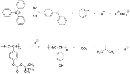
Based on the chemical structure of photoresists, they can be classified into three types: photopolymeric, photodecomposing, photocrosslinking photoresist.
Photopolymeric photoresist is a type of photoresist, usually allyl monomer, which could generate free radical when exposed to light, then initiates the photopolymerization of monomer to produce a polymer. Photopolymeric photoresists are usually used for negative photoresist, e.g. methyl methacrylate.
Photodecomposing photoresist is a type of photoresist that generates hydrophilic products under light. Photodecomposing photoresists are usually used for positive photoresist. A typical example is azide quinone, e.g. diazonaphthaquinone (DQ).
Photocrosslinking photoresist is a type of photoresist, which could crosslink chain by chain when exposed to light, to generate an insoluble network. Photocrosslinking photoresist are usually used for negative photoresist.
Off-Stoichiometry Thiol-Enes (OSTE) polymers[7]
For self-assembled monolayer SAM photoresist, first a SAM is formed on the substrate by self-assembly. Then, this surface covered by SAM is irradiated through a mask, similar to other photoresist, which generates a photo-patterned sample in the irradiated areas. And finally developer is used to remove the designed part (could be used as both positive or negative photoresist).[8]
Chromatic correction of visible and near infrared wavelengths. Horizontal axis shows degree of aberration, 0 is no aberration. Lenses: 1: simple, 2: achromatic doublet, 3: apochromatic and 4: superachromat.
https://en.wikipedia.org/wiki/Photoresist
In optics, the f-number of an optical system such as a camera lens is the ratio of the system's focal length to the diameter of the entrance pupil ("clear aperture").[1][2][3] It is also known as the focal ratio, f-ratio, or f-stop, and is very important in photography.[4] It is a dimensionless number that is a quantitative measure of lens speed; increasing the f-number is referred to as stopping down. The f-number is commonly indicated using a lower-case hooked f with the format f/N, where N is the f-number.
The f-number is the reciprocal of the relative aperture (the aperture diameter divided by focal length).[5]
https://en.wikipedia.org/wiki/F-number
Fresnel zone antennas are antennas that focus the signal by using the phase shifting property of the antenna surface or its shape[1][2] [3] .[4][5] There are several types of Fresnel zone antennas, namely, Fresnel zone plate, offset Fresnel zone plate antennas, phase correcting reflective array or "Reflectarray" antennas and 3 Dimensional Fresnel antennas. They are a class of diffractive antennas and have been used from radio frequencies to X rays.
Fresnel zone antennas belong to the category of reflector and Lens antennas. Unlike traditional reflector and lens antennas, however, the focusing effect in a Fresnel zone antenna is achieved by controlling the phase shifting property of the surface and allows for flat[1][6] or arbitrary antenna shapes.[4] For historical reasons, a flat Fresnel zone antenna is termed a Fresnel zone plate antenna. An offset Fresnel zone plate can be flush mounted to the wall or roof of a building, printed on a window, or made conformal to the body of a vehicle.[7]
The advantages of the Fresnel zone plate antenna are numerous. It is normally cheap to manufacture and install, easy to transport and package and can achieve high gain. Owing to its flat nature, the wind loading force of a Fresnel zone plate can be as little as 1/8 of that of conventional solid or wire-meshed reflectors of similar size. When used at millimetre wave frequencies, a Fresnel zone antenna can be an integrated with the millimetre-wave monolithic integrated circuit (MMIC) and thus becomes even more competitive than a printed antenna array.
The simplest Fresnel zone plate antenna is the circular half-wave zone plate invented in the nineteenth century. The basic idea is to divide a plane aperture into circular zones with respect to a chosen focal point on the basis that all radiation from each zone arrives at the focal point in phase within ±π/2 range. If the radiation from alternate zones is suppressed or shifted in phase by π, an approximate focus is obtained and a feed can be placed there to collect the received energy effectively. Despite its simplicity, the half-wave zone plate remained mainly as an optical device for a long time, primarily because its efficiency is too low (less than 20%) and the sidelobe level of its radiation pattern is too high to compete with conventional reflector antennas.
Compared with conventional reflector and lens antennas, reported research on microwave and millimetre-wave Fresnel zone antennas appears to be limited. In 1948, Maddaus published the design and experimental work on stepped half-wave lens antennas operating at 23 GHz and sidelobe levels of around -17 dB were achieved. In 1961, Buskirk and Hendrix reported an experiment on simple circular phase reversal zone plate reflector antennas for radio frequency operation. Unfortunately, the sidelobe they achieved was as high as −7 dB. In 1987, Black and Wiltse published their theoretical and experimental work on the stepped quarter-wave zone plate at 35 GHz. A sidelobe level of about −17 dB was achieved. A year later a phase reversal zone plate reflector operating at 94 GHz was reported by Huder and Menzel, and 25% efficiency and −19 dB sidelobe level were obtained. An experiment on a similar antenna at 11.8 GHz was reported by NASA researchers in 1989. 5% 3 dB bandwidth and −16 dB sidelobe level were measured.[1]
Until the 1980s, the Fresnel zone plate antenna was regarded as a poor candidate for microwave applications. Following the development of DBSservices in the eighties, however, antenna engineers began to consider the use of Fresnel zone plates as candidate antennas for DBS reception, where antenna cost is an important factor. This, to some extent, provided a commercial push to the research on Fresnel zone antennas.[1][3][5]
Offset Fresnel antenna[edit]
The offset Fresnel zone plate was first reported in.[8] In contrast to the symmetrical Fresnel zone plate which consists of a set of circular zones, the offset Fresnel zone plate consists of a set of elliptical zones defined by

where a, b and c are determined by the offset angle and focal length and the zone index. This feature introduces some new problems to the analysis of offset Fresnel zone plate antennas. The formulae and algorithms for predicting the radiation pattern of an offset Fresnel lens antenna are presented in,[8]where some experimental results are also reported. Although a simple Fresnel lens antenna has low efficiency, it serves as a very attractive indoor candidate when a large window or an electrically transparent wall is available. In the application of direct broadcasting services (DBS), for example, an offset Fresnel lens can be produced by simply painting a zonal pattern on a window glass or a blind with conducting material. The satellite signal passing through the transparent zones is then collected by using an indoor feed.
Phase correcting antenna[edit]
To increase the efficiency of Fresnel zone plate antennas, one can divide each Fresnel zone into several sub-zones, such as quarter-wave sub-zones, and provide an appropriate phase shift in each of them, thus resulting in a sub-zone phase correcting zone plate.[9] The problem with dielectric based zone plate lens antenna is that whilst a dielectric is providing a phase shift to the transmitted wave, it inevitably reflects some of the energy back, so the efficiency of such a lens is limited. However, the low efficiency problem for a zone plate reflector is less severe, as total reflection can achieved by using a conducting reflector behind the zone plate.[10] Based on the focal field analysis, it is demonstrated that high efficiency zone plate reflectors can be obtained by employing the multilayer phase correcting technique, which is to use a number of dielectric slabs of low permittivity and print different metallic zonal patterns on the different interfaces. The design and experiments of circular and offset multilayer phase correcting zone plate reflectors were presented in.[1]
A problem with the multilayer zone plate reflector is the complexity introduced, which might offset the advantage of using Fresnel zone plate antennas. One solution is to print an inhomogeneous array of conducting elements on a grounded dielectric plate, thus leading to the so-called single-layer printed flat reflector.[1][11] This configuration bears much in common with the printed array antenna but it requires the use of a feed antenna instead of a corporate feed network. In contract to the normal array antenna, the array elements are different and are arranged in a pseudo-periodic manner. The theory and design method of single layer printed flat reflectors incorporating conducting rings and experimental results on such an antenna operating in the X-band were given in.[5] Naturally, this leads to a more general antenna concept, the phase correcting reflective array.
Reflectarray antenna[edit]

A phase correcting reflective array consists of an array of phase shifting elements illuminated by a feed placed at the focal point. The word "reflective" refers to the fact that each phase shifting element reflects back the energy in the incident wave with an appropriate phase shift. The phase shifting elements can be passive or active. Each phase shifting element can be designed to either produce a phase shift which is equal to that required at the element centre, or provide some quantised phase shifting values. Although the former does not seem to be commercially attractive, the latter proved to be practical antenna configuration. One potential advantage is that such an array can be reconfigured by changing the positions of the elements to produce different radiation patterns. A systematic theory of the phase efficiency of passive phase correcting array antennas and experimental results on an X-band prototype were reported in.[1] In recent years, it became common to call this type of antennas "reflectarrays".[12]
Reference phase modulation[edit]
It has been shown that the phase of the main lobe of a zone plate follows its reference phase,[13] a constant path length or phase added to the formula for the zones, but that the phase of the side lobes is much less sensitive.

So, when it is possible to modulate the signal by changing the material properties dynamically, the modulation of the side lobes is much less than that of the main lobe and so they disappear on demodulation, leaving a cleaner and more private signal.[14]
Beamsteering Fresnel antennes[edit]
Beamsteering can be applied by amplitude/phase control or amplitude-only control of the elements of an antenna array positioned in the focal point of the lens as antenna feed. With amplitude-only control, no bandwidth-limiting phase shifters are needed, saving complexity and alleviating bandwidth constraints at the cost of limited beamsteering capability.[15]
Three-dimensional Fresnel antennas[edit]
In order to increase the focusing, resolving and scanning properties and to create different shaped radiation patterns the Fresnel zone plate and antenna can be assembled conformable to a curvilinear natural or man-made formation and used as a diffractive antenna-Radome.[4]
https://en.wikipedia.org/wiki/Fresnel_zone_antenna
In optics, chromatic aberration (CA), also called chromatic distortion and spherochromatism, is a failure of a lens to focus all colors to the same point.[1] It is caused by dispersion: the refractive index of the lens elements varies with the wavelength of light. The refractive index of most transparent materials decreases with increasing wavelength.[2] Since the focal length of a lens depends on the refractive index, this variation in refractive index affects focusing.[3] Chromatic aberration manifests itself as "fringes" of color along boundaries that separate dark and bright parts of the image.
| Optical aberration |
|---|
|
There are two types of chromatic aberration: axial (longitudinal), and transverse (lateral). Axial aberration occurs when different wavelengths of light are focused at different distances from the lens (focus shift). Longitudinal aberration is typical at long focal lengths. Transverse aberration occurs when different wavelengths are focused at different positions in the focal plane, because the magnification and/or distortion of the lens also varies with wavelength. Transverse aberration is typical at short focal lengths. The ambiguous acronym LCA is sometimes used for either longitudinal or lateral chromatic aberration.[2]
The two types of chromatic aberration have different characteristics, and may occur together. Axial CA occurs throughout the image and is specified by optical engineers, optometrists, and vision scientists in diopters.[4] It can be reduced by stopping down, which increases depth of field so that though the different wavelengths focus at different distances, they are still in acceptable focus. Transverse CA does not occur in the center of the image and increases towards the edge. It is not affected by stopping down.
In digital sensors, axial CA results in the red and blue planes being defocused (assuming that the green plane is in focus), which is relatively difficult to remedy in post-processing, while transverse CA results in the red, green, and blue planes being at different magnifications (magnification changing along radii, as in geometric distortion), and can be corrected by radially scaling the planes appropriately so they line up.
Comparison of an ideal image of a ring (1) and ones with only axial (2) and only transverse (3) chromatic aberration
https://en.wikipedia.org/wiki/Chromatic_aberration


Parameters[edit]
Physical, chemical and optical properties of photoresists influence their selection for different processes.[14]
- Resolution is the ability to differ the neighboring features on the substrate. Critical dimension (CD) is a main measure of resolution.
The smaller the critical dimension is, the higher resolution would be.
- Contrast is the difference from exposed portion to unexposed portion. The higher the contrast is, the more obvious the difference between exposed and unexposed portions would be.
- Sensitivity is the minimum energy that is required to generate a well-defined feature in the photoresist on the substrate, measured in mJ/cm2. The sensitivity of a photoresist is important when using deep ultraviolet (DUV) or extreme-ultraviolet (EUV).
- Viscosity is a measure of the internal friction of a fluid, affecting how easily it will flow. When it is needed to produce a thicker layer, a photoresist with higher viscosity will be preferred.
- Adherence is the adhesive strength between photoresist and substrate. If the resist comes off the substrate, some features will be missing or damaged.
- Anti-etching is the ability of a photoresist to resist the high temperature, different pH environment or the ion bombardment in the process of post-modification.
- Surface tension is the tension that induced by a liquid tended to minimize its surface area, which is caused by the attraction of the particles in the surface layer. In order to better wet the surface of substrate, photoresists are required to possess relatively low surface tension.
Epoxy-based polymer[edit]
One very common negative photoresist is based on epoxy-based polymer. The common product name is SU-8 photoresist, and it was originally invented by IBM, but is now sold by Microchem and Gersteltec. One unique property of SU-8 is that it is very difficult to strip. As such, it is often used in applications where a permanent resist pattern (one that is not strippable, and can even be used in harsh temperature and pressure environments) is needed for a device.[15] Mechanism of epoxy-based polymer is shown in 1.2.3 SU-8.
Off-stoichiometry thiol-enes(OSTE) polymer[edit]
In 2016, OSTE Polymers were shown to possess a unique photolitography mechanism, based on diffusion-induced monomer depletion, which enables high photostructuring accuracy. The OSTE polymer material was originally invented at the KTH Royal Institute of Technology, but is now sold by Mercene Labs. Whereas the material has properties similar to those of SU8, OSTE has the specific advantage that it contains reactive surface molecules, which make this material attractive for microfluidic or biomedical applications.[14]
Microcontact printing[edit]
Microcontact printing was described by Whitesides Group in 1993. Generally, in this techniques, an elastomeric stamp is used to generate two-dimensional patterns, through printing the “ink” molecules onto the surface of a solid substrate.[16]


Step 1 for microcontact printing. A scheme for the creation of a polydimethylsiloxane (PDMS) master stamp. Step 2 for microcontact printing A scheme of the inking and contact process of microprinting lithography.
Printed circuit boards[edit]
The manufacture of printed circuit boards is one of the most important uses of photoresist. Photolithography allows the complex wiring of an electronic system to be rapidly, economically, and accurately reproduced as if run off a printing press. The general process is applying photoresist, exposing image to ultraviolet rays, and then etching to remove the copper-clad substrate.[17]

Patterning and etching of substrates[edit]
This includes specialty photonics materials, MicroElectro-Mechanical Systems (MEMS), glass printed circuit boards, and other micropatterning tasks. Photoresist tends not to be etched by solutions with a pH greater than 3.[18]

Microelectronics[edit]
This application, mainly applied to silicon wafers/silicon integrated circuits is the most developed of the technologies and the most specialized in the field.[19]
A photopolymer or light-activated resin is a polymer that changes its properties when exposed to light, often in the ultraviolet or visible region of the electromagnetic spectrum.[1] These changes are often manifested structurally, for example hardening of the material occurs as a result of cross-linkingwhen exposed to light. An example is shown below depicting a mixture of monomers, oligomers, and photoinitiators that conform into a hardened polymeric material through a process called curing.[2][3]
A wide variety of technologically useful applications rely on photopolymers, for example some enamels and varnishes depend on photopolymer formulation for proper hardening upon exposure to light. In some instances, an enamel can cure in a fraction of a second when exposed to light, as opposed to thermally cured enamels which can require half an hour or longer.[4] Curable materials are widely used for medical, printing, and photoresisttechnologies.

Changes in structural and chemical properties can be induced internally by chromophoresthat the polymer subunit already possesses, or externally by addition of photosensitivemolecules. Typically a photopolymer consists of a mixture of multifunctional monomers and oligomers in order to achieve the desired physical properties, and therefore a wide variety of monomers and oligomers have been developed that can polymerize in the presence of light either through internal or external initiation. Photopolymers undergo a process called curing, where oligomers are cross-linked upon exposure to light, forming what is known as a network polymer. The result of photo-curing is the formation of a thermoset network of polymers. One of the advantages of photo-curing is that it can be done selectively using high energy light sources, for example lasers, however, most systems are not readily activated by light, and in this case a photoinitiator is required. Photoinitiators are compounds that upon radiation of light decompose into reactive species that activate polymerization of specific functional groups on the oligomers.[5] An example of a mixture that undergoes cross-linking when exposed to light is shown below. The mixture consists of monomeric styrene and oligomeric acrylates.[6]

Most commonly, photopolymerized systems are typically cured through UV radiation, since ultraviolet light is more energetic. However, the development of dye-based photoinitiator systems have allowed for the use of visible light, having the potential advantages of being simpler and safer to handle.[7] UV curing in industrial processes has greatly expanded over the past several decades. Many traditional thermally cured and solvent-based technologies can be replaced by photopolymerization technologies. The advantages of photopolymerization over thermally cured polymerization include higher rates of polymerization and environmental benefits from elimination of volatile organic solvents.[1]
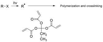
There are two general routes for photoinitiation: free radical and ionic.[1][4] The general process involves doping a batch of neat polymer with small amounts of photoinitiator, followed by selective radiation of light, resulting in a highly cross-linked product. Many of these reactions do not require solvent which eliminates termination path via reaction of initiators with solvent and impurities, in addition to decreasing the overall cost.[8]
https://en.wikipedia.org/wiki/Photopolymer
detailed knowledge of the optical system used to produce the image can allow for some useful correction.[13]
Chromatic aberration is used during a duochrome eye test to ensure that a correct lens power has been selected. The patient is confronted with red and green images and asked which is sharper. If the prescription is right, then the cornea, lens and prescribed lens will focus the red and green wavelengths just in front, and behind the retina, appearing of equal sharpness. If the lens is too powerful or weak, then one will focus on the retina, and the other will be much more blurred in comparison.[12]
In an ideal situation, post-processing to remove or correct lateral chromatic aberration would involve scaling the fringed color channels, or subtracting some of a scaled versions of the fringed channels, so that all channels spatially overlap each other correctly in the final image.[14]
https://en.wikipedia.org/wiki/Chromatic_aberration
The Cooke triplet is a photographic lens designed and patented (patent number GB 22,607) in 1893 by Dennis Taylor who was employed as chief engineer by T. Cooke & Sons of York. It was the first lens system that allowed elimination of most of the optical distortion or aberration at the outer edge of lenses.[citation needed]
The Cooke triplet is noted for being able to correct the Seidel aberrations.[1] It is recognized as one of the most important objective designs in the field of photography.[2][3]
The lens designed, invented by Dennis Taylor but named for the firm he worked for, consists of three separated lens elements.[2] It has two biconvex lenses on the outer and a biconcave lens in the middle.[2]
The design took a new approach to solving the optical design issues, and the design was presented to the Optical Society of London.[4]
https://en.wikipedia.org/wiki/Cooke_triplet
Category:Light-sensitive chemicals
Chemicals that will react under influence of light.
Pages in category "Light-sensitive chemicals"
The following 12 pages are in this category, out of 12 total. This list may not reflect recent changes (learn more).
https://en.wikipedia.org/wiki/Category:Light-sensitive_chemicals
In optics, aberration is a property of optical systems, such as lenses, that causes light to be spread out over some region of space rather than focused to a point.[1] Aberrations cause the image formed by a lens to be blurred or distorted, with the nature of the distortion depending on the type of aberration. Aberration can be defined as a departure of the performance of an optical system from the predictions of paraxial optics.[2] In an imaging system, it occurs when light from one point of an object does not converge into (or does not diverge from) a single point after transmission through the system. Aberrations occur because the simple paraxial theory is not a completely accurate model of the effect of an optical system on light, rather than due to flaws in the optical elements.[3]
An image-forming optical system with aberration will produce an image which is not sharp. Makers of optical instruments need to correct optical systems to compensate for aberration.
Aberration can be analyzed with the techniques of geometrical optics. The articles on reflection, refractionand caustics discuss the general features of reflected and refracted rays.
https://en.wikipedia.org/wiki/Optical_aberration
A waveplate or retarder is an optical device that alters the polarization state of a light wave travelling through it. Two common types of waveplates are the half-wave plate, which shifts the polarization direction of linearly polarized light, and the quarter-wave plate, which converts linearly polarized light into circularly polarized light and vice versa.[1] A quarter-wave plate can be used to produce elliptical polarization as well.
Waveplates are constructed out of a birefringent material (such as quartz or mica, or even plastic), for which the index of refraction is different for light linearly polarized along one or the other of two certain perpendicular crystal axes. The behavior of a waveplate (that is, whether it is a half-wave plate, a quarter-wave plate, etc.) depends on the thickness of the crystal, the wavelength of light, and the variation of the index of refraction. By appropriate choice of the relationship between these parameters, it is possible to introduce a controlled phase shift between the two polarization components of a light wave, thereby altering its polarization.[1]
A common use of waveplates—particularly the sensitive-tint (full-wave) and quarter-wave plates—is in optical mineralogy. Addition of plates between the polarizers of a petrographic microscopemakes the optical identification of minerals in thin sections of rocks easier,[2] in particular by allowing deduction of the shape and orientation of the optical indicatrices within the visible crystal sections. This alignment can allow discrimination between minerals which otherwise appear very similar in plane polarized and cross polarized light.
https://en.wikipedia.org/wiki/Waveplate#Half-wave_plate
Wind loads on buildings[edit]
The design of buildings must account for wind loads, and these are affected by wind shear. For engineering purposes, a power law wind-speed profile may be defined as:[5][6]

where:
- = speed of the wind at height
- = gradient wind at gradient height
- = exponential coefficient


Typically, buildings are designed to resist a strong wind with a very long return period, such as 50 years or more. The design wind speed is determined from historical records using extreme value theory to predict future extreme wind speeds. Wind speeds are generally calculated based on some regional design standard or standards. The design standards for building wind loads include:
- AS 1170.2 for Australia
- EN 1991-1-4 for Europe
- NBC for Canada
Wind engineering is a subset of mechanical engineering, structural engineering, meteorology, and applied physics that analyzes the effects of wind in the natural and the built environment and studies the possible damage, inconvenience or benefits which may result from wind. In the field of engineering it includes strong winds, which may cause discomfort, as well as extreme winds, such as in a tornado, hurricane or heavy storm, which may cause widespread destruction. In the fields of wind energy and air pollution it also includes low and moderate winds as these are relevant to electricity production and dispersion of contaminants.
Wind engineering draws upon meteorology, fluid dynamics, mechanics, geographic information systems, and a number of specialist engineering disciplines, including aerodynamics and structural dynamics.[1] The tools used include atmospheric models, atmospheric boundary layer wind tunnels, and computational fluid dynamics models.
Wind engineering involves, among other topics:
- Wind impact on structures (buildings, bridges, towers)
- Wind comfort near buildings
- Effects of wind on the ventilation system in a building
- Wind climate for wind energy
- Air pollution near buildings
Wind engineering may be considered by structural engineers to be closely related to earthquake engineering and explosion protection.
Some sports stadiums such as Candlestick Park and Arthur Ashe Stadium are known for their strong, sometimes swirly winds, which affect the playing conditions.
A lens antenna is a microwave antenna that uses a shaped piece of microwave-transparent material to bend and focus the radio waves by refraction, as an optical lens does for light.[1] Typically it consists of a small feed antenna such as a patch antenna or horn antenna which radiates radio waves, with a piece of dielectric or composite material in front which functions as a converging lens to collimate the radio waves into a beam.[2]Conversely, in a receiving antenna the lens focuses the incoming radio waves onto the feed antenna, which converts them to electric currents which are delivered to a radio receiver. They can also be fed by an array of feed antennas, called a focal plane array (FPA), to create more complicated radiation patterns.
To generate narrow beams, the lens must be much larger than the wavelength of the radio waves, so lens antennas are mainly used at the high frequency end of the radio spectrum, with microwaves and millimeter waves, whose small wavelengths allow the antenna to be a manageable size. The lens can be made of a dielectric material like plastic, or a composite structure of metal plates or waveguides.[3] Its principle of operation is the same as an optical lens: the microwaves have a different speed (phase velocity) within the lens material than in air, so that the varying lens thickness delays the microwaves passing through it by different amounts, changing the shape of the wavefront and the direction of the waves.[2] Lens antennas can be classified into two types: delay lens antennas in which the microwaves travel slower in the lens material than in air, and fast lens antennas in which the microwaves travel faster in the lens material. As with optical lenses, geometric optics are used to design lens antennas, and the different shapes of lenses used in ordinary optics have analogues in microwave lenses.
Lens antennas have similarities to parabolic antennas and are used in similar applications. In both, microwaves emitted by a small feed antenna are shaped by a large optical surface into the desired final beam shape.[4] They are used less than parabolic antennas due to chromatic aberration and absorption of microwave power by the lens material, their greater weight and bulk, and difficult fabrication and mounting.[3] They are used as collimating elements in high gain microwave systems, such as satellite antennas, radio telescopes, and millimeter wave radar and are mounted in the apertures of horn antennas to increase gain.
https://en.wikipedia.org/wiki/Lens_antenna
A zone plate is a device used to focus light or other things exhibiting wave character.[1] Unlike lenses or curved mirrors, zone plates use diffraction instead of refraction or reflection. Based on analysis by French physicist Augustin-Jean Fresnel, they are sometimes called Fresnel zone plates in his honor. The zone plate's focusing ability is an extension of the Arago spot phenomenon caused by diffraction from an opaque disc.[2]
A zone plate consists of a set of concentric rings, known as Fresnel zones, which alternate between being opaqueand transparent. Light hitting the zone plate will diffract around the opaque zones. The zones can be spaced so that the diffracted light constructively interferes at the desired focus, creating an image there.
https://en.wikipedia.org/wiki/Zone_plate
Opacity is the measure of impenetrability to electromagnetic or other kinds of radiation, especially visible light. In radiative transfer, it describes the absorption and scattering of radiation in a medium, such as a plasma, dielectric, shielding material, glass, etc. An opaque object is neither transparent (allowing all light to pass through) nor translucent (allowing some light to pass through). When light strikes an interface between two substances, in general some may be reflected, some absorbed, some scattered, and the rest transmitted (also see refraction). Reflection can be diffuse, for example light reflecting off a white wall, or specular, for example light reflecting off a mirror. An opaque substance transmits no light, and therefore reflects, scatters, or absorbs all of it. Both mirrors and carbon black are opaque. Opacity depends on the frequency of the light being considered. For instance, some kinds of glass, while transparent in the visual range, are largely opaque to ultraviolet light. More extreme frequency-dependence is visible in the absorption lines of cold gases. Opacity can be quantified in many ways; for example, see the article mathematical descriptions of opacity.
Different processes can lead to opacity including absorption, reflection, and scattering.
https://en.wikipedia.org/wiki/Opacity_(optics)
A photon sieve is a device for focusing light using diffraction and interference. It consists of a flat sheet of material full of pinholes that are arranged in a pattern which is similar to the rings in a Fresnel zone plate, but a sieve brings light to much sharper focus than a zone plate. The sieve concept, first developed in 2001,[1] is versatile because the characteristics of the focusing behaviour can be altered to suit the application by manufacturing a sieve containing holes of several different sizes and different arrangement of the pattern of holes.
Photon sieves have applications to photolithography.[2] and are an alternative to lenses or mirrors in telescopes[3] and terahertz lenses and antennas.[4][conflicted source][5]
When the size of sieves is smaller than one wavelength of operating light, the traditional method mentioned above to describe the diffraction patterns is not valid. The vertorial theory must be used to approximate the diffraction of light from nanosieves.[6] In this theory, the combination of coupled-mode theory and multiple expansion method is used to give an analytical model, which can facilitate the demonstration of traditional devices such as lens, holograms, etc.[7]
https://en.wikipedia.org/wiki/Photon_sieve
Terahertz radiation – also known as submillimeter radiation, terahertz waves, tremendously high frequency[1] (THF), T-rays, T-waves, T-light, T-lux or THz – consists of electromagnetic waves within the ITU-designated band of frequencies from 0.3 to 3 terahertz (THz),[2] although the upper boundary is somewhat arbitrary and is considered by some sources as 30 THz.[3] One terahertz is 1012 Hz or 1000 GHz. Wavelengths of radiation in the terahertz band correspondingly range from 1 mm to 0.01 mm = 10 µm. Because terahertz radiation begins at a wavelength of around 1 millimeter and proceeds into shorter wavelengths, it is sometimes known as the submillimeter band, and its radiation as submillimeter waves, especially in astronomy. This band of electromagnetic radiation lies within the transition region between microwave and far infrared, and can be regarded as either.
Terahertz radiation is strongly absorbed by the gases of the atmosphere, and in air is attenuated to zero within a few meters,[4][5] so it is not practical for terrestrial radio communication. It can penetrate thin layers of materials but is blocked by thicker objects. THz beams transmitted through materials can be used for material characterization, layer inspection, and as a lower-energy alternative to X-rays for producing high resolution images of the interior of solid objects.[6]
Terahertz radiation occupies a middle ground where the ranges of microwaves and infrared light waves overlap, known as the “terahertz gap”; it is called a “gap” because the technology for its generation and manipulation is still in its infancy. The generation and modulation of electromagnetic waves in this frequency range ceases to be possible by the conventional electronic devices used to generate radio waves and microwaves, requiring the development of new devices and techniques.
https://en.wikipedia.org/wiki/Terahertz_radiation
A lens antenna is a microwave antenna that uses a shaped piece of microwave-transparent material to bend and focus the radio waves by refraction, as an optical lens does for light.[1] Typically it consists of a small feed antenna such as a patch antenna or horn antenna which radiates radio waves, with a piece of dielectric or composite material in front which functions as a converging lens to collimate the radio waves into a beam.[2]Conversely, in a receiving antenna the lens focuses the incoming radio waves onto the feed antenna, which converts them to electric currents which are delivered to a radio receiver. They can also be fed by an array of feed antennas, called a focal plane array (FPA), to create more complicated radiation patterns.
To generate narrow beams, the lens must be much larger than the wavelength of the radio waves, so lens antennas are mainly used at the high frequency end of the radio spectrum, with microwaves and millimeter waves, whose small wavelengths allow the antenna to be a manageable size. The lens can be made of a dielectric material like plastic, or a composite structure of metal plates or waveguides.[3] Its principle of operation is the same as an optical lens: the microwaves have a different speed (phase velocity) within the lens material than in air, so that the varying lens thickness delays the microwaves passing through it by different amounts, changing the shape of the wavefront and the direction of the waves.[2] Lens antennas can be classified into two types: delay lens antennas in which the microwaves travel slower in the lens material than in air, and fast lens antennas in which the microwaves travel faster in the lens material. As with optical lenses, geometric optics are used to design lens antennas, and the different shapes of lenses used in ordinary optics have analogues in microwave lenses.
Lens antennas have similarities to parabolic antennas and are used in similar applications. In both, microwaves emitted by a small feed antenna are shaped by a large optical surface into the desired final beam shape.[4] They are used less than parabolic antennas due to chromatic aberration and absorption of microwave power by the lens material, their greater weight and bulk, and difficult fabrication and mounting.[3] They are used as collimating elements in high gain microwave systems, such as satellite antennas, radio telescopes, and millimeter wave radar and are mounted in the apertures of horn antennas to increase gain.
Types[edit]
Microwave lenses can be classified into two types by the propagation speed of the radio waves in the lens material:[2]
- Delay lens (slow wave lens): in this type the radio waves travel slower in the lens medium than in free space; the index of refraction is greater than one, so the path length is increased by passing through the lens medium. This is similar to the action of an ordinary optical lens on light. Since thicker parts of the lens increase the path length, a convex lens is a converging lens which focuses radio waves, and a concave lens is a diverging lens which disperses radio waves, as in ordinary lenses. Delay lenses are constructed of
- Dielectric materials
- H-plane plate structures
- Fast lens (fast wave lens): in this type the radio waves travel faster in the lens medium than in free space, so the index of refraction is less than one, so the optical path length is decreased by passing through the lens medium. This type has no analog in ordinary optical materials, it occurs because the phase velocity of radio waves in waveguides can be greater than the speed of light. Since thicker parts of the lens decrease path length, a concave lens is a converging lens which focuses radio waves, and a convex lens is a diverging lens, the opposite of ordinary optical lenses. Fast lenses are constructed of
- E-plane plate structures
- Negative-index metamaterials

The main types of lens construction are:[5][6]
- Natural dielectric lens - A lens made of a piece of dielectric material. Due to the longer wavelength, microwave lenses have much larger surface shape tolerances than optical lenses. Soft thermoplastics such as polystyrene, polyethylene, and plexiglass are often used, which can be molded or turned to the required shape. Most dielectric materials have significant attenuation and dispersion at microwave frequencies.
- Artificial dielectric lens - This simulates the properties of a dielectric at microwave wavelengths by a 3 dimensional array of small metal conductors, such as spheres, strips, discs or rings suspended in a nonconducting support medium

- Constrained lens - a lens composed of structures that control the direction of the microwaves. They are used with linearly polarized microwaves.
- E-plane metal plate lens - a lens made of closely spaced metal plates parallel to the plane of the electric or E field. This is a fast lens.
- H-plane metal plate lens - a lens made of closely spaced metal plates parallel to the plane of the magnetic or H field. This is a delay lens.
- Waveguide lens - A lens made of short sections of waveguide of different lengths
- Fresnel zone lens - A flat Fresnel zone plate, consisting of concentric annular sheet metal rings blocking out alternate Fresnel zones. It can be easily fabricated with copper foil shapes on a printed circuit board. This lens works by diffraction, not refraction. The microwaves passing through the spaces between the plates interfere constructively at the focal plane. It has large chromatic aberration and so is frequency-specific.
- Luneburg lens - A spherical dielectric lens with a stepped or graded index of refraction increasing toward the center.[7] Luneburg lens antennas have several unique features: the focal point, and the feed antenna, is located at the surface of the lens, so it focuses all the radiation from the feed over a wide angle. It can be used with multiple feed antennas to create multiple beams.
Zoned lens - Microwave lenses, especially short wavelength designs, tend to be excessively thick. This increases weight, bulk, and power losses in dielectric lenses. To reduce thickness, lenses are often made with a zoned geometry, similar to a Fresnel lens. The lens is cut down to a uniform thickness in concentric annular (circular) steps, keeping the same surface angle.[8][9] To keep the microwaves passing through different steps in phase, the height difference between steps must be an integral multiple of a wavelength. For this reason a zoned lens must be made for a specific frequency
Experiment demonstrating refraction of 1.5 GHz (20 cm) microwaves by a paraffin lens, by John Ambrose Fleming in 1897, repeating earlier experiments by Bose, Lodge, and Righi. A spark gap transmitter (A), consisting of a dipole antenna made of two brass rods with a spark gap between them inside an open waveguide, powered by an induction coil (I) generates a beam of microwaves which is focused by the cylindrical paraffin lens (L) on a dipole receiving antenna in the lefthand waveguide (B) and detected by a coherer radio receiver (not shown), which rang a bell every time the transmitter was pulsed. Fleming demonstrated that the lens actually focused the waves by showing that when it was removed from the apparatus, the unfocused waves from the transmitter were too weak to activate the receiver.
The first experiments using lenses to refract and focus radio waves occurred during the earliest research on radio waves in the 1890s. In 1873 mathematical physicist James Clerk Maxwell in his electromagnetic theory, now called Maxwell's equations, predicted the existence of electromagnetic waves and proposed that light consisted of electromagnetic waves of very short wavelength. In 1887 Heinrich Hertz discovered radio waves, electromagnetic waves of longer wavelength. Early scientists thought of radio waves as a form of "invisible light". To test Maxwell's theory that light was electromagnetic waves, these researchers concentrated on duplicating classic optics experiments with short wavelength radio waves, diffractingthem with wire diffraction gratings and refracting them with dielectric prismsand lenses of paraffin, pitch and sulfur. Hertz first demonstrated refraction of 450 MHz (66 cm) radio waves in 1887 using a 6 foot prism of pitch. These experiments among others confirmed that light and radio waves both consisted of the electromagnetic waves predicted by Maxwell, differing only in frequency.
The possibility of concentrating radio waves by focusing them into a beam like light waves interested many researchers of the time.[10] In 1889 Oliver Lodge and James L. Howard attempted to refract 300 MHz (1 meter) waves with cylindrical lenses made of pitch, but failed to find a focusing effect because the apparatus was smaller than the wavelength. In 1894 Lodge successfully focused 4 GHz (7.5 cm) microwaves with a 23 cm glass lens.[11]Beginning the same year, Indian physicist Jagadish Chandra Bose in his landmark 6 - 60 GHz (25 to 5 mm) microwave experiments may have been the first to construct lens antennas, using a 2.5 cm cylindrical sulfur lens in a waveguide to collimate the microwave beam from his spark oscillator,[12] and patenting a receiving antenna consisting of a glass lens focusing microwaves on a galena crystal detector.[13] Also in 1894 Augusto Righi in his microwave experiments at University of Bologna focused 12 GHz (3 cm) waves with 32 cm lenses of paraffin and sulfur. However, microwaves were limited to line-of-sight propagation and could not travel beyond the horizon, and the low power microwave spark transmitters used had very short range. So the practical development of radio after 1897 used much lower frequencies, for which lens antennas were not suitable.
The development of modern lens antennas occurred during a great expansion of research into microwave technology around World War 2 to develop military radar. In 1946 R. K. Luneberg invented the Luneberg lens.
https://en.wikipedia.org/wiki/Lens_antenna
An antenna reflector is a device that reflects electromagnetic waves. Antenna reflectors can exist as a standalone device for redirecting radio frequency (RF) energy, or can be integrated as part of an antennaassembly.
The function of a standalone reflector is to redirect electro-magnetic (EM) energy, generally in the radio wavelength range of the electromagnetic spectrum.
Common standalone reflector types are
- corner reflector, which reflects the incoming signal back to the direction from which it came, commonly used in radar.
- flat reflector, which reflects the signal such as a mirror and is often used as a passive repeater.
When integrated into an antenna assembly, the reflector serves to modify the radiation pattern of the antenna, increasing gain in a given direction.
Common integrated reflector types are
- parabolic reflector, which focuses a beam signal into one point or directs a radiating signal into a beam.[1]
- a passive element slightly longer than and located behind a radiating dipole element that absorbs and re-radiates the signal in a directional way as in a Yagi antenna array.
- a flat reflector such as used in a Short backfire antenna or Sector antenna.
- a corner reflector used in UHF television antennas.
- a cylindrical reflector as used in Cantenna.
Parameters that can directly influence the performance of an antenna with integrated reflector:
- Dimensions of the reflector (Big ugly dish versus small dish)
- Spillover (part of the feed antenna radiation misses the reflector)
- Aperture blockage (also known as feed blockage: part of the feed energy is reflected back into the feed antenna and does not contribute to the main beam)
- Illumination taper (feed illumination reduced at the edges of the reflector)
- Reflector surface deviation
- Defocusing
- Cross polarization
- Feed losses
- Antenna feed mismatch
- Non-uniform amplitude/phase distributions
The antenna efficiency is measured in terms of its effectiveness ratio.
Any gain-degrading factors which raise side lobes have a two-fold effect, in that they contribute to system noise temperature in addition to reducing gain. Aperture blockage and deviation of reflector surface (from the designed "ideal") are two important cases. Aperture blockage is normally due to shadowing by feed, subreflector and/or support members. Deviations in reflector surfaces cause non-uniform aperture distributions, resulting in reduced gains.
The standard symmetrical, parabolic, Cassegrain reflector system is very popular in practice because it allows minimum feeder length to the terminal equipment. The major disadvantage of this configuration is blockage by the hyperbolic sub-reflector and its supporting struts (usually 3–4 are used). The blockage becomes very significant when the size of the parabolic reflector is small compared to the diameter of the sub-reflector. To avoid blockage from the sub-reflector asymmetric designs such as the open Cassegrain can be employed. Note however that the asymmetry can have deleterious effects on some aspects of the antenna's performance - for example, inferior side-lobe levels, beam squint, poor cross-polar response, etc.
To avoid spillover from the effects of over-illumination of the main reflector surface and diffraction, a microwave absorber is sometimes employed. This lossy material helps prevent excessive side-lobe levels radiating from edge effects and over-illumination. Note that in the case of a front-fed Cassegrain the feed horn and feeder (usually waveguide) need to be covered with an edge absorber in addition to the circumference of the main paraboloid.
Measurements are made on reflector antennas to establish important performance indicators such as the gain and sidelobe levels. For this purpose the measurements must be made at a distance at which the beam is fully formed. A distance of four Rayleigh distances is commonly adopted as the minimum distance at which measurements can be made, unless specialized techniques are used (see Antenna measurement).
https://en.wikipedia.org/wiki/Reflector_(antenna)
Polarization (also polarisation) is a property applying to transverse waves that specifies the geometrical orientation of the oscillations.[1][2][3][4][5] In a transverse wave, the direction of the oscillation is perpendicular to the direction of motion of the wave.[4] A simple example of a polarized transverse wave is vibrations traveling along a taut string (see image); for example, in a musical instrument like a guitar string. Depending on how the string is plucked, the vibrations can be in a vertical direction, horizontal direction, or at any angle perpendicular to the string. In contrast, in longitudinal waves, such as sound waves in a liquid or gas, the displacement of the particles in the oscillation is always in the direction of propagation, so these waves do not exhibit polarization. Transverse waves that exhibit polarization include electromagnetic waves such as light and radio waves, gravitational waves,[6] and transverse sound waves (shear waves) in solids.
An electromagnetic wave such as light consists of a coupled oscillating electric field and magnetic fieldwhich are always perpendicular to each other; by convention, the "polarization" of electromagnetic waves refers to the direction of the electric field. In linear polarization, the fields oscillate in a single direction. In circular or elliptical polarization, the fields rotate at a constant rate in a plane as the wave travels. The rotation can have two possible directions; if the fields rotate in a right hand sense with respect to the direction of wave travel, it is called right circular polarization, while if the fields rotate in a left hand sense, it is called left circular polarization.
Light or other electromagnetic radiation from many sources, such as the sun, flames, and incandescent lamps, consists of short wave trains with an equal mixture of polarizations; this is called unpolarized light. Polarized light can be produced by passing unpolarized light through a polarizer, which allows waves of only one polarization to pass through. The most common optical materials do not affect the polarization of light, however, some materials—those that exhibit birefringence, dichroism, or optical activity—affect light differently depending on its polarization. Some of these are used to make polarizing filters. Light is also partially polarized when it reflects from a surface.
According to quantum mechanics, electromagnetic waves can also be viewed as streams of particles called photons. When viewed in this way, the polarization of an electromagnetic wave is determined by a quantum mechanical property of photons called their spin.[7][8] A photon has one of two possible spins: it can either spin in a right hand sense or a left hand sense about its direction of travel. Circularly polarized electromagnetic waves are composed of photons with only one type of spin, either right- or left-hand. Linearly polarized waves consist of photons that are in a superposition of right and left circularly polarized states, with equal amplitude and phases synchronized to give oscillation in a plane.[8]
Polarization is an important parameter in areas of science dealing with transverse waves, such as optics, seismology, radio, and microwaves. Especially impacted are technologies such as lasers, wireless and optical fiber telecommunications, and radar.
https://en.wikipedia.org/wiki/Polarization_(waves)
In antenna engineering, side lobes or sidelobes are the lobes (local maxima) of the far field radiation pattern of an antenna or other radiation source, that are not the main lobe.
The radiation pattern of most antennas shows a pattern of "lobes" at various angles, directions where the radiated signal strength reaches a maximum, separated by "nulls", angles at which the radiated signal strength falls to zero. This can be viewed as the diffraction pattern of the antenna. In a directional antenna in which the objective is to emit the radio waves in one direction, the lobe in that direction is designed to have a larger field strength than the others; this is the "main lobe". The other lobes are called "side lobes", and usually represent unwanted radiation in undesired directions. The side lobe directly behind the main lobe is called the back lobe. The longer the antenna relative to the radio wavelength, the more lobes its radiation pattern has. In transmittingantennas, excessive side lobe radiation wastes energy and may cause interference to other equipment. Another disadvantage is that confidential information may be picked up by unintended receivers. In receiving antennas, side lobes may pick up interfering signals, and increase the noise level in the receiver.
The power density in the side lobes is generally much less than that in the main beam. It is generally desirable to minimize the sidelobe level (SLL), which is measured in decibels relative to the peak of the main beam. The main lobe and side lobes occur for both transmitting and receiving. The concepts of main and side lobes, radiation pattern, aperture shapes, and aperture weighting, apply to optics (another branch of electromagnetics) and in acoustics fields such as loudspeaker and sonar design, as well as antenna design.
Because an antenna's far field radiation pattern is a Fourier Transform of its aperture distribution, most antennas will generally have sidelobes, unless the aperture distribution is a Gaussian, or if the antenna is so small as to have no sidelobes in the visible space. Larger antennas have narrower main beams, as well as narrower sidelobes. Hence, larger antennas have more sidelobes in the visible space (as the antenna size is increased, sidelobes move from the evanescent space to the visible space).
For discrete aperture antennas (such as phased arrays) in which the element spacing is greater than a half wavelength, the spatial aliasing effect causes some sidelobes to become substantially larger in amplitude, and approaching the level of the main lobe; these are called grating lobes, and they are identical, or nearly identical in the example shown, copies of the main beams.
Grating lobes side lobe main lobeare a special case of a sidelobe. In such a case, the sidelobes should be considered all the lobes lying between the main lobe and the first grating lobe, or between grating lobes. It is conceptually useful to distinguish between sidelobes and grating lobes because grating lobes have larger amplitudes than most, if not all, of the other side lobes. The mathematics of grating lobes is the same as of X-ray diffraction.
https://en.wikipedia.org/wiki/Side_lobe
In electronics, noise temperature is one way of expressing the level of available noise power introduced by a component or source. The power spectral density of the noise is expressed in terms of the temperature (in kelvins) that would produce that level of Johnson–Nyquist noise, thus:

where:
- is the noise power (in W, watts)
- is the total bandwidth (Hz, hertz) over which that noise power is measured
- is the Boltzmann constant (1.381×10⁻²³ J/K, joules per kelvin)
- is the noise temperature (K, kelvin)


Thus the noise temperature is proportional to the power spectral density of the noise, . That is the power that would be absorbed from the component or source by a matched load. Noise temperature is generally a function of frequency, unlike that of an ideal resistor which is simply equal to the actual temperature of the resistor at all frequencies.

https://en.wikipedia.org/wiki/Noise_temperature
The Cassegrain reflector is a combination of a primary concave mirror and a secondary convex mirror, often used in optical telescopes and radio antennas, the main characteristic being that the optical path folds back onto itself, relative to the optical system's primary mirror entrance aperture. This design puts the focal point at a convenient location behind the primary mirror and the convex secondary adds a telephoto effect creating a much longer focal length in a mechanically short system.[1]
In a symmetrical Cassegrain both mirrors are aligned about the optical axis, and the primary mirror usually contains a hole in the center, thus permitting the light to reach an eyepiece, a camera, or an image sensor. Alternatively, as in many radio telescopes, the final focus may be in front of the primary. In an asymmetrical Cassegrain, the mirror(s) may be tilted to avoid obscuration of the primary or to avoid the need for a hole in the primary mirror (or both).
The classic Cassegrain configuration uses a parabolic reflector as the primary while the secondary mirror is hyperbolic.[2] Modern variants may have a hyperbolic primary for increased performance (for example, the Ritchey–Chrétien design); and either or both mirrors may be spherical or elliptical for ease of manufacturing.
The Cassegrain reflector is named after a published reflecting telescope design that appeared in the April 25, 1672 Journal des sçavans which has been attributed to Laurent Cassegrain.[3] Similar designs using convex secondary mirrors have been found in the Bonaventura Cavalieri's 1632 writings describing burning mirrors[4][5] and Marin Mersenne's 1636 writings describing telescope designs.[6] James Gregory's 1662 attempts to create a reflecting telescope included a Cassegrain configuration, judging by a convex secondary mirror found among his experiments.[7]
The Cassegrain design is also used in catadioptric systems.
An unusual variant of the Cassegrain is the Schiefspiegler telescope ("skewed" or "oblique reflector"; also known as the "Kutter telescope" after its inventor, Anton Kutter[9]) which uses tilted mirrors to avoid the secondary mirror casting a shadow on the primary. However, while eliminating diffraction patterns this leads to several other aberrations that must be corrected.
Several different off-axis configurations are used for radio antennas.[10]
Another off-axis, unobstructed design and variant of the Cassegrain is the 'Yolo' reflector invented by Arthur Leonard. This design uses a spherical or parabolic primary and a mechanically warped spherical secondary to correct for off-axis induced astigmatism. When set up correctly the Yolo can give uncompromising unobstructed views of planetary objects and non-wide field targets, with no lack of contrast or image quality caused by spherical aberration. The lack of obstruction also eliminates the diffraction associated with Cassegrain and Newtonian reflector astrophotography.


Catadioptric Cassegrains[edit]
Catadioptric Cassegrains use two mirrors, often with a spherical primary mirror to reduce cost, combined with refractive corrector element(s) to correct the resulting aberrations.
Schmidt-Cassegrain[edit]
The Schmidt-Cassegrain was developed from the wide-field Schmidt camera, although the Cassegrain configuration gives it a much narrower field of view. The first optical element is a Schmidt corrector plate. The plate is figured by placing a vacuum on one side, and grinding the exact correction required to correct the spherical aberration caused by the spherical primary mirror. Schmidt-Cassegrains are popular with amateur astronomers. An early Schmidt-Cassegrain camera was patented in 1946 by artist/architect/physicist Roger Hayward,[11] with the film holder placed outside the telescope.
Maksutov-Cassegrain[edit]
The Maksutov-Cassegrain is a variation of the Maksutov telescope named after the Soviet/Russian opticianand astronomer Dmitri Dmitrievich Maksutov. It starts with an optically transparent corrector lens that is a section of a hollow sphere. It has a spherical primary mirror, and a spherical secondary that is usually a mirrored section of the corrector lens.
Argunov-Cassegrain[edit]
In the Argunov-Cassegrain telescope all optics are spherical, and the classical Cassegrain secondary mirror is replaced by a sub-aperture corrector consisting of three air spaced lens elements. The element farthest from the primary mirror is a Mangin mirror, which acts as a secondary mirror.
Klevtsov-Cassegrain[edit]
The Klevtsov-Cassegrain, like the Argunov-Cassegrain, uses a sub-aperture corrector consisting of a small meniscus lens and a Mangin mirror as its "secondary mirror".[12]
https://en.wikipedia.org/wiki/Cassegrain_reflector
A catadioptric optical system is one where refraction and reflection are combined in an optical system, usually via lenses (dioptrics) and curved mirrors (catoptrics). Catadioptric combinations are used in focusing systems such as searchlights, headlamps, early lighthouse focusing systems, optical telescopes, microscopes, and telephoto lenses. Other optical systems that use lenses and mirrors are also referred to as "catadioptric", such as surveillancecatadioptric sensors.
https://en.wikipedia.org/wiki/Catadioptric_system
n a phased array or slotted waveguide antenna, squint refers to the angle that the transmission is offset from the normal of the plane of the antenna. In simple terms, it is the change in the beam direction as a function of operating frequency, polarization, or orientation.[1] It is an important phenomenon that can limit the bandwidth in phased array antenna systems.[2]
This deflection can be caused by:
- Signal frequency
- Signals in a waveguide travel at a speed that varies with frequency and the dimensions of the waveguide.
In a phased array or slotted waveguide antenna, the signal is designed to reach the outputs in a given phase relationship. This can be accomplished for any single frequency by properly adjusting the length of each waveguide so the signals arrive in-phase. However, if a different frequency is sent into the feeds, they will arrive at the ends at different times, the phase relationship will not be maintained,[3] and squint will result.
Frequency-dependant phase shifting of the elements of the array can be used to compensate for the squint,[4] which leads to the concept of a squintless antenna or feed.[5]
- Design
- In some cases the antenna may be designed to create a squint. For example, an antenna which is used to communicate with a satellite but must remain in a vertical configuration. Squint is also required in conical scanning.
- https://en.wikipedia.org/wiki/Squint_(antenna)
A radome (a portmanteau of radar and dome) is a structural, weatherproof enclosure that protects a radarantenna. The radome is constructed of material that minimally attenuates the electromagnetic signaltransmitted or received by the antenna, effectively transparent to radio waves. Radomes protect the antenna from weather and conceal antenna electronic equipment from view. They also protect nearby personnel from being accidentally struck by quickly rotating antennas.
Radomes can be constructed in several shapes – spherical, geodesic, planar, etc. – depending on the particular application, using various construction materials such as fiberglass, polytetrafluoroethylene (PTFE)-coated fabric, and others.
When found on fixed-wing aircraft with forward-looking radar, as are commonly used for object or weather detection, the nose cones often additionally serve as radomes. On aircraft used for airborne early warning and control (AEW&C), a rotating radome, often called a "rotodome", is mounted on the top of the fuselage for 360-degree coverage. Some newer AEW&C configurations instead use three antenna modules inside a radome, usually mounted on top of the fuselage, for 360-degree coverage, such as the Chinese KJ-2000 and Indian DRDO AEW&Cs.
On rotary-wing and fixed-wing aircraft using microwave satellite for beyond-line-of-sight communication, radomes often appear as blisters on the fuselage.[1] In addition to protection, radomes also streamline the antenna system, thus reducing drag.
A radome is often used to prevent ice and freezing rain from accumulating on antennas. In the case of a spinning radar parabolic antenna, the radome also protects the antenna from debris and rotational irregularities due to wind. Its shape is easily identified by its hardshell, which has strong properties against being damaged.
One of the main driving forces behind the development of fiberglass as a structural material was the need during World War II for radomes.[2] When considering structural load, the use of a radome greatly reduces wind load in both normal and iced conditions. Many tower sites require or prefer the use of radomes for wind loading benefits and for protection from falling ice or debris.
Where radomes might be considered unsightly if near the ground, electric antenna heaters could be used instead. Usually running on direct current, the heaters do not interfere physically or electrically with the alternating current of the radio transmission.
https://en.wikipedia.org/wiki/Radome
In the field of antenna design the term radiation pattern (or antenna pattern or far-field pattern) refers to the directional (angular) dependence of the strength of the radio waves from the antenna or other source.[1][2][3]
Particularly in the fields of fiber optics, lasers, and integrated optics, the term radiation pattern may also be used as a synonym for the near-field pattern or Fresnel pattern.[4] This refers to the positional dependence of the electromagnetic field in the near field, or Fresnel region of the source. The near-field pattern is most commonly defined over a plane placed in front of the source, or over a cylindrical or spherical surface enclosing it.[1][4]
The far-field pattern of an antenna may be determined experimentally at an antenna range, or alternatively, the near-field pattern may be found using a near-field scanner, and the radiation pattern deduced from it by computation.[1] The far-field radiation pattern can also be calculated from the antenna shape by computer programs such as NEC. Other software, like HFSS can also compute the near field.
The far field radiation pattern may be represented graphically as a plot of one of a number of related variables, including; the field strength at a constant (large) radius (an amplitude pattern or field pattern), the power per unit solid angle (power pattern) and the directive gain. Very often, only the relative amplitude is plotted, normalized either to the amplitude on the antenna boresight, or to the total radiated power. The plotted quantity may be shown on a linear scale, or in dB. The plot is typically represented as a three-dimensional graph (as at right), or as separate graphs in the vertical plane and horizontal plane. This is often known as a polar diagram.
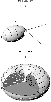 Three-dimensional antenna radiation patterns. The radial distance from the origin in any direction represents the strength of radiation emitted in that direction. The top shows the directive pattern of a horn antenna, the bottom shows the omnidirectional pattern of a simple vertical antenna.
Typical polar radiation plot. Most antennas show a pattern of "lobes" or maxima of radiation. In a directive antenna, shown here, the largest lobe, in the desired direction of propagation, is called the "main lobe". The other lobes are called "sidelobes" and usually represent radiation in unwanted directions.
For a complete proof, see the reciprocity (electromagnetism) article. Here, we present a common simple proof limited to the approximation of two antennas separated by a large distance compared to the size of the antenna, in a homogeneous medium. The first antenna is the test antenna whose patterns are to be investigated; this antenna is free to point in any direction. The second antenna is a reference antenna, which points rigidly at the first antenna.
https://en.wikipedia.org/wiki/Radiation_pattern

The E-plane and H-plane are reference planes for linearly polarized waveguides, antennas and other microwave devices.
In waveguide systems, as in the electric circuits, it is often desirable to be able to split the circuit power into two or more fractions. In a waveguide system, an element called a junction is used for power division.
In a low frequency electrical network, it is possible to combine circuit elements in series or in parallel, thereby dividing the source power among several circuit components. In microwave circuits, a waveguide with three independent ports is called a TEE junction. The output of E-Plane Tee is 180° out of phase where the output of H-plane Tee is in phase.[1]
E-Plane[edit]
For a linearly-polarized antenna, this is the plane containing the electric field vector (sometimes called the E aperture) and the direction of maximum radiation. The electric field or "E" plane determines the polarization or orientation of the radio wave. For a vertically polarized antenna, the E-plane usually coincides with the vertical/elevation plane. For a horizontally polarized antenna, the E-Plane usually coincides with the horizontal/azimuth plane. E- plane and H-plane should be 90 degrees apart.
H-plane[edit]
In the case of the same linearly polarized antenna, this is the plane containing the magnetic field vector (sometimes called the H aperture) and the direction of maximum radiation. The magnetizing field or "H" plane lies at a right angle to the "E" plane. For a vertically polarized antenna, the H-plane usually coincides with the horizontal/azimuth plane. For a horizontally polarized antenna, the H-plane usually coincides with the vertical/elevation plane.
Diagram showing the relationship between the E and H planes for a vertically polarized omnidirectional dipole antenna
https://en.wikipedia.org/wiki/E-plane_and_H-plane
A photonic integrated circuit (PIC) or integrated optical circuit is a device that integrates multiple (at least two) photonic functions and as such is similar to an electronic integrated circuit. The major difference between the two is that a photonic integrated circuit provides functions for information signals imposed on optical wavelengths typically in the visible spectrum or near infrared 850 nm-1650 nm.
The most commercially utilized material platform for photonic integrated circuits is indium phosphide (InP), which allows for the integration of various optically active and passive functions on the same chip. Initial examples of photonic integrated circuits were simple 2-section distributed Bragg reflector(DBR) lasers, consisting of two independently controlled device sections - a gain section and a DBR mirror section. Consequently, all modern monolithic tunable lasers, widely tunable lasers, externally modulated lasers and transmitters, integrated receivers, etc. are examples of photonic integrated circuits. As of 2012, devices integrate hundreds of functions onto a single chip.[1] Pioneering work in this arena was performed at Bell Laboratories. The most notable academic centers of excellence of photonic integrated circuits in InP are the University of California at Santa Barbara, USA, and the Eindhoven University of Technology in the Netherlands.
A 2005 development[2] showed that silicon can, even though it is an indirect bandgap material, still be used to generate laser light via the Raman nonlinearity. Such lasers are not electrically driven but optically driven and therefore still necessitate a further optical pump laser source.
Examples of photonic integrated circuits[edit]
The primary application for photonic integrated circuits is in the area of fiber-optic communication though applications in other fields such as biomedicaland photonic computing are also possible.
The arrayed waveguide grating (AWG) which are commonly used as optical (de)multiplexers in wavelength division multiplexed (WDM) fiber-optic communication systems are an example of a photonic integrated circuit which has replaced previous multiplexing schemes which utilized multiple discrete filter elements. Since separating optical modes is a need for quantum computing, this technology may be helpful to miniaturize quantum computers (see linear optical quantum computing).
Another example of a photonic integrated chip in wide use today in fiber-optic communication systems is the externally modulated laser (EML) which combines a distributed feed back laser diode with an electro-absorption modulator[4] on a single InP based chip.
Current status[edit]
Photonic integration is currently an active topic in U.S. Defense contracts.[5][6] It is included by the Optical Internetworking Forum for inclusion in 100 gigahertz optical networking standards.[7]
https://en.wikipedia.org/wiki/Photonic_integrated_circuit
Linear Optical Quantum Computing or Linear Optics Quantum Computation (LOQC) is a paradigm of quantum computation, allowing (under certain conditions, described below) universal quantum computation. LOQC uses photons as information carriers, mainly uses linear optical elements, or optical instruments (including reciprocal mirrors and waveplates) to process quantum information, and uses photon detectors and quantum memories to detect and store quantum information.[1][2][3]
https://en.wikipedia.org/wiki/Linear_optical_quantum_computing
Single-photon sources are light sources that emit light as single particles or photons. They are distinct from coherent light sources (lasers) and thermal light sources such as incandescent light bulbs. The Heisenberg uncertainty principle dictates that a state with an exact number of photons of a single frequency cannot be created. However, Fock states (or number states) can be studied for a system where the electric field amplitude is distributed over a narrow bandwidth. In this context, a single-photon source gives rise to an effectively one-photon number state. Photons from an ideal single-photon source exhibit quantum mechanical characteristics. These characteristics include photon antibunching, so that the time between two successive photons is never less than some minimum value. This is normally demonstrated by using a beam splitter to direct about half of the incident photons toward one avalanche photodiode, and half toward a second. Pulses from one detector are used to provide a ‘counter start’ signal, to a fast electronic timer, and the other, delayed by a known number of nanoseconds, is used to provide a ‘counter stop’ signal. By repeatedly measuring the times between ‘start’ and ‘stop’ signals, one can form a histogram of time delay between two photons and the coincidence count- if bunching is not occurring, and photons are indeed well spaced, a clear notch around zero delay is visible.
https://en.wikipedia.org/wiki/Single-photon_source
A distributed feedback laser (DFB) is a type of laser diode, quantum cascade laser or optical fiber laser where the active region of the device contains a periodically structured element or diffraction grating. The structure builds a one-dimensional interference grating (Bragg scattering) and the grating provides optical feedback for the laser. This longitudinal diffraction grating has periodic changes in refractive index that cause reflection back into the cavity. The periodic change can be either in the real part of the refractive index, or in the imaginary part (gain or absorption). The strongest grating operates in the first order - where the periodicity is one-half wave, and the light is reflected backwards. DFB lasers tend to be much more stable than Fabry-Perot or DBR lasers and are used frequently when clean single mode operation is needed, especially in high speed fiber optic telecommunications. Semiconductor DFB lasers in the lowest loss window of optical fibers at about 1.55um wavelength, amplified by Erbium-doped fiber amplifiers (EDFAs), dominate the long distance communication market, while DFB lasers in the lowest dispersion window at 1.3um are used at shorter distances.
The simplest kind of a laser is a Fabry-Perot laser, where there are two broad-band reflectors at the two ends of the lasing optical cavity. The light bounces back and forth between these two mirrors and forms longitudinal modes or standing waves. The back reflector is generally high reflectivity, and the front mirror is lower reflectivity. The light then leaks out of the front mirror and forms the output of the laser diode. Since the mirrors are generally broad-band and reflect many wavelengths, the laser supports multiple longitudinal modes, or standing waves, simultaneously and lases multimode, or easily jumps between longitudinal modes. If the temperature of a semiconductor Fabry-Perot laser changes, the wavelengths that are amplified by the lasing medium vary rapidly. At the same time, the longitudinal modes of the laser also vary, as the refractive index is also a function of temperature. This causes the spectrum to be unstable and highly temperature dependent. At the important wavelengths of 1.55um and 1.3um, the peak gain typically moves about 0.4nm to the longer wavelengths as the temperature increases, while the longitudinal modes shift about 0.1nm to the longer wavelengths.
If one or both of these end mirrors are replaced with a diffraction grating, the structure is then known as a DBR laser (Distributed Bragg Reflector). These longitudinal diffraction grating mirrors reflect the light back in the cavity, very much like a multi-layer mirror coating. The diffraction grating mirrors tend to reflect a narrower band of wavelengths than normal end mirrors, and this limits the number of standing waves that can be supported by the gain in the cavity. So DBR lasers tend to be more spectrally stable than Fabry-Perot lasers with broadband coatings. Nevertheless, as the temperature or current changes in the laser, the device can "mode-hop" jumping from one standing wave to another. The overall shifts with temperature are however lower with DBR lasers as the mirrors determine which longitudinal modes lase, and they shift with the refractive index and not the peak gain.
In a DFB laser, the grating and the reflection is generally continuous along the cavity, instead of just being at the two ends. This changes the modal behavior considerably and makes the laser more stable. There are various designs of DFB lasers, each with slightly different properties.
If the grating is periodic and continuous, and the ends of the laser are anti-reflection (AR/AR) coated, so there is no feedback other than the grating itself, then such a structure supports two longitudinal (degenerate) modes and almost always lases at two wavelengths. Obviously a two-moded laser is generally not desirable. So there are various ways of breaking this "degeneracy".
The first is by inducing a quarter-wave shift in the cavity. This phase-shift acts like a "defect" and creates a resonance in the center of the reflectivity bandwidth or "stop-band." The laser then lases at this resonance and is extremely stable. As the temperature and current changes, the grating and the cavity shift together at the lower rate of the refractive index change, and there are no mode-hops. However, light is emitted from both sides of the lasers, and generally the light from one side is wasted. Furthermore, creating an exact quarter-wave shift can be technologically difficult to achieve, and often requires directly-written electron-beam lithography. Often, rather than a single quarter-wave phase shift at the center of the cavity, multiple smaller shifts distributed in the cavity at different locations that spread out the mode longitudinally and give higher output power.
An alternate way of breaking this degeneracy is by coating the back end of the laser to a high reflectivity (HR). The exact position of this end reflector cannot be accurately controlled, and so one obtains a random phase shift between the grating and the exact position of the end mirror. Sometimes this leads to a perfect phase shift, where effectively a quarter-wave phase shifted DFB is reflected on itself. In this case all the light exits the front facet and one obtains a very stable laser. At other times, however, the phase shift between the grating and the high-reflector back mirror is not optimal, and one ends up with a two-moded lasers again. Additionally, the phase of the cleave affects the wavelength, and thus controlling the output wavelength of a batch of lasers in manufacturing can be a challenge.[1] Thus the HR/AR DFB lasers tend to be low yield and have to be screened before use. There are various combinations of coatings and phase shifts that can be optimized for power and yield, and generally each manufacturer has their own technique to optimize performance and yield.
To encode data on a DFB laser for fiber optic communications, generally the electric drive current is varied to modulate the intensity of the light. These DMLs (Directly modulated lasers) are the simplest kinds and are found in various fiber optic systems. The disadvantage of directly modulating a laser is that there are associated frequency shifts together with the intensity shifts (laser chirp). These frequency shifts, together with dispersion in the fiber, cause the signal to degrade after some distance, limiting the bandwidth and the range. An alternate structure is an electro-absorption modulated laser (EML) that runs the laser continuously and has a separate section integrated in front that either absorbs or transmits the light - very much like an optical shutter. These EMLs can operate at higher speeds and have much lower chirp. In very high performance coherent optical communication systems, the DFB laser is run continuously and is followed by a phase modulator. On the receiving end, a local oscillator DFB interferes with the received signal and decodes the modulation.
An alternative approach is a phase-shifted DFB laser. In this case both facets are anti-reflection coated and there is a phase shift in the cavity. Such devices have much better reproducibility in wavelength and theoretically all lase in single mode.
In DFB fiber lasers the Bragg grating (which in this case forms also the cavity of the laser) has a phase-shift centered in the reflection band akin to a single very narrow transmission notch of a Fabry–Pérot interferometer. When configured properly, these lasers operate on a single longitudinal mode with coherence lengths in excess of tens of kilometres, essentially limited by the temporal noise induced by the self-heterodyne coherence detection technique used to measure the coherence. These DFB fibre lasers are often used in sensing applications where extreme narrow line width is required.
References[edit]
- ^ See for example: Yariv, Amnon (1985). Quantum Electronics (3rd ed.). New York: Holt, Reinhart and Wilson. pp. 421–429.
- B. Mroziewicz, "Physics of Semiconductor Lasers", pp. 348 - 364. 1991.
- J. Carroll, J. Whiteaway and D. Plumb, "Distributed Feedback Semiconductor Lasers", IEE Circuits, Devices and Systems Series 10, London (1998)
External links[edit]
https://en.wikipedia.org/wiki/Distributed_feedback_laser
Electro-absorption modulator
An electro-absorption modulator (EAM) is a semiconductor device which can be used for modulating the intensity of a laser beam via an electric voltage. Its principle of operation is based on the Franz–Keldysh effect, i.e., a change in the absorption spectrum caused by an applied electric field, which changes the bandgap energy (thus the photon energy of an absorption edge) but usually does not involve the excitation of carriers by the electric field.
For modulators in telecommunications, small size and modulation voltages are desired. The EAM is candidate for use in external modulation links in telecommunications. These modulators can be realized using either bulk semiconductor materials or materials with multiple quantum dots or wells.
Most EAMs are made in the form of a waveguide with electrodes for applying an electric field in a direction perpendicular to the modulated light beam. For achieving a high extinction ratio, one usually exploits the Quantum-confined Stark effect (QCSE) in a quantum well structure.
Compared with an Electro-optic modulator (EOM), an EAM can operate with much lower voltages (a few volts instead of ten volts or more). They can be operated at very high speed; a modulation bandwidth of tens of gigahertz can be achieved, which makes these devices useful for optical fiber communication. A convenient feature is that an EAM can be integrated with distributed feedback laser diode on a single chip to form a data transmitter in the form of a photonic integrated circuit. Compared with direct modulation of the laser diode, a higher bandwidth and reduced chirp can be obtained.
Semiconductor quantum well EAM is widely used to modulate near-infrared (NIR) radiation at frequencies below 0.1 THz. Here, the NIR absorption of undoped quantum well was modulated by strong electric field with frequencies between 1.5 and 3.9 THz. The THz field coupled two excited states (excitons) of the quantum wells, as manifested by a new THz frequency-and power- dependent NIR absorption line. The THz field generated a coherent quantum superposition of an absorbing and a nonabsorbing exciton. This quantum coherence may yield new applications for quantum well modulators in optical communications.
Recently, advances in crystal growth have triggered the study of self organized quantum dots. Since the EAM requires small size and low modulation voltages, possibility of obtaining quantum dots with enhanced electro-absorption coefficients makes them attractive for such application.
See also[edit]
References[edit]
- S. G. Carter, Quantum Coherence in an Optical Modulator, Science 310 (2005) 651
- I. B. Akca, Electro-optic and electro-absorption characterization of InAs quantum dot waveguides, Opt. Exp. 16 (2008) 3439
- X. Xu, Coherent Optical Spectroscopy of a Strongle Driven Quantum Dot, Science 317 (2007) 929
https://en.wikipedia.org/wiki/Electro-absorption_modulator
An optical transistor, also known as an optical switch or a light valve, is a device that switches or amplifies optical signals. Light occurring on an optical transistor’s input changes the intensity of light emitted from the transistor’s output while output power is supplied by an additional optical source. Since the input signal intensity may be weaker than that of the source, an optical transistor amplifies the optical signal. The device is the optical analog of the electronic transistor that forms the basis of modern electronic devices. Optical transistors provide a means to control light using only light and has applications in optical computing and fiber-optic communication networks. Such technology has the potential to exceed the speed of electronics[citation needed], while conserving more power.
Since photons inherently do not interact with each other, an optical transistor must employ an operating medium to mediate interactions. This is done without converting optical to electronic signals as an intermediate step. Implementations using a variety of operating mediums have been proposed and experimentally demonstrated. However, their ability to compete with modern electronics is currently limited.
Optical transistors could in theory be impervious to the high radiation of space and extraterrestrial planets, unlike electronic transistors which suffer from Single-event upset.
Perhaps the most significant advantage of optical over electronic logic is reduced power consumption. This comes from the absence of capacitance in the connections between individual logic gates. In electronics, the transmission line needs to be charged to the signal voltage. The capacitance of a transmission line is proportional to its length and it exceeds the capacitance of the transistors in a logic gate when its length is equal to that of a single gate. The charging of transmission lines is one of the main energy losses in electronic logic. This loss is avoided in optical communication where only enough energy to switch an optical transistor at the receiving end must be transmitted down a line. This fact has played a major role in the uptake of fiber optics for long distance communication but is yet to be exploited at the microprocessor level.
Several schemes have been proposed to implement all-optical transistors. In many cases, a proof of concept has been experimentally demonstrated. Among the designs are those based on:
- electromagnetically induced transparency
- in an optical cavity or microresonator, where the transmission is controlled by a weaker flux of gate photons[5][6]
- in free space, i.e., without a resonator, by addressing strongly interacting Rydberg states[7][8]
- a system of indirect excitons (composed of bound pairs of electrons and holes in double quantum wells with a static dipole moment). Indirect excitons, which are created by light and decay to emit light, strongly interact due to their dipole alignment.[9][10]
- a system of microcavity polaritons (exciton-polaritons inside an optical microcavity) where, similar to exciton-based optical transistors, polaritonsfacilitate effective interactions between photons[11]
- photonic crystal cavities with an active Raman gain medium[12]
- cavity switch modulates cavity properties in time domain for quantum information applications.[13]
- nanowire-based cavities employing polaritonic interactions for optical switching[14]
- silicon microrings placed in the path of an optical signal. Gate photons heat the silicon microring causing a shift in the optical resonant frequency, leading to a change in transparency at a given frequency of the optical supply.[15]
- a dual-mirror optical cavity that holds around 20,000 cesium atoms trapped by means of optical tweezers and laser-cooled to a few microkelvin. The cesium ensemble did not interact with light and was thus transparent. The length of a round trip between the cavity mirrors equaled an integer multiple of the wavelength of the incident light source, allowing the cavity to transmit the source light. Photons from the gate light field entered the cavity from the side, where each photon interacted with an additional "control" light field, changing a single atom's state to be resonant with the cavity optical field, which changing the field's resonance wavelength and blocking transmission of the source field, thereby "switching" the "device". While the changed atom remains unidentified, quantum interference allows the gate photon to be retrieved from the cesium. A single gate photon could redirect a source field containing up to two photons before the retrieval of the gate photon was impeded, above the critical threshold for a positive gain.[16]
See also[edit]
https://en.wikipedia.org/wiki/Optical_transistor
A single-event upset (SEU) is a change of state caused by one single ionizing particle (ions, electrons, photons...) striking a sensitive node in a micro-electronic device, such as in a microprocessor, semiconductor memory, or power transistors. The state change is a result of the free charge created by ionization in or close to an important node of a logic element (e.g. memory "bit"). The error in device output or operation caused as a result of the strike is called an SEU or a soft error.
The SEU itself is not considered permanently damaging to the transistor's or circuits' functionality unlike the case of single-event latch-up (SEL), single-event gate rupture (SEGR), or single-event burnout (SEB). These are all examples of a general class of radiation effects in electronic devices called single-event effects (SEEs).
Single-event upsets were first described during above-ground nuclear testing, from 1954 to 1957, when many anomalies were observed in electronic monitoring equipment. Further problems were observed in space electronics during the 1960s, although it was difficult to separate soft failures from other forms of interference. In 1972, a Hughes satellite experienced an upset where the communication with the satellite was lost for 96 seconds and then recaptured. Scientists Dr. Edward C. Smith, Al Holman, and Dr. Dan Binder explained the anomaly as a single-event upset (SEU) and published the first SEU paper in the IEEE Transactions on Nuclear Science journal in 1975.[2] In 1978, the first evidence of soft errors from alpha particles in packaging materials was described by Timothy C. May and M.H. Woods. In 1979, James Ziegler of IBM, along with W. Lanford of Yale, first described the mechanism whereby a sea-level cosmic ray could cause a single event upset in electronics. 1979 also saw the world’s first heavy ion “single event effects” test at a particle accelerator facility, conducted at Lawrence Berkeley National Laboratory's 88-Inch Cyclotron and Bevatron.[3]
Terrestrial SEU arise due to cosmic particles colliding with atoms in the atmosphere, creating cascades or showers of neutrons and protons, which in turn may interact with electronic circuits. At deep sub-micron geometries, this affects semiconductor devices in the atmosphere.
In space, high-energy ionizing particles exist as part of the natural background, referred to as galactic cosmic rays (GCR). Solar particle events and high-energy protons trapped in the Earth's magnetosphere (Van Allen radiation belts) exacerbate this problem. The high energies associated with the phenomenon in the space particle environment generally render increased spacecraft shielding useless in terms of eliminating SEU and catastrophic single-event phenomena (e.g. destructive latch-up). Secondary atmospheric neutrons generated by cosmic rays can also have sufficiently high energy for producing SEUs in electronics on aircraft flights over the poles or at high altitude. Trace amounts of radioactive elements in chip packages also lead to SEUs.
The sensitivity of a device to SEU can be empirically estimated by placing a test device in a particle stream at a cyclotron or other particle acceleratorfacility. This particular test methodology is especially useful for predicting the SER (soft error rate) in known space environments, but can be problematic for estimating terrestrial SER from neutrons. In this case, a large number of parts must be evaluated, possibly at different altitudes, to find the actual rate of upset.
Another way to empirically estimate SEU tolerance is to use a chamber shielded for radiation, with a known radiation source, such as Caesium-137.
When testing microprocessors for SEU, the software used to exercise the device must also be evaluated to determine which sections of the device were activated when SEUs occurred.
By definition, SEUs do not destroy the circuits involved, but they can cause errors. In space-based microprocessors, one of the most vulnerable portions is often the 1st and 2nd-level cache memories, because these must be very small and have very high-speed, which means that they do not hold much charge. Often these caches are disabled if terrestrial designs are being configured to survive SEUs. Another point of vulnerability is the state machine in the microprocessor control, because of the risk of entering "dead" states (with no exits), however, these circuits must drive the entire processor, so they have relatively large transistors to provide relatively large electric currents and are not as vulnerable as one might think. Another vulnerable processor component is the RAM. To ensure resilience to SEUs, often an error correcting memory is used, together with circuitry to periodically read (leading to correction) or scrub (if reading does not lead to correction) the memory of errors, before the errors overwhelm the error-correcting circuitry.
In digital and analog circuits, a single event may cause one or more voltages pulses (i.e. glitches) to propagate through the circuit, in which case it is referred to as a single-event transient (SET). Since the propagating pulse is not technically a change of "state" as in a memory SEU, one should differentiate between SET and SEU. If a SET propagates through digital circuitry and results in an incorrect value being latched in a sequential logic unit, it is then considered an SEU.
Hardware problems can also occur for related reasons. Under certain circumstances (of both circuit design, process design, and particle properties) a "parasitic" thyristor inherent to CMOS designs can be activated, effectively causing an apparent short-circuit from power to ground. This condition is referred to as latch-up, and in absence of constructional countermeasures, often destroys the device due to thermal runaway. Most manufacturers design to prevent latch-up, and test their products to ensure that latch-up does not occur from atmospheric particle strikes. In order to prevent latch-up in space, epitaxial substrates, silicon on insulator (SOI) or silicon on sapphire (SOS) are often used to further reduce or eliminate the susceptibility.
https://en.wikipedia.org/wiki/Single-event_upset
Radiation hardening is the process of making electronic components and circuits resistant to damage or malfunction caused by high levels of ionizing radiation (particle radiation and high-energy electromagnetic radiation),[1] especially for environments in outer space (especially beyond the low Earth orbit), around nuclear reactors and particle accelerators, or during nuclear accidents or nuclear warfare.
Most semiconductor electronic components are susceptible to radiation damage, and radiation-hardened components are based on their non-hardened equivalents, with some design and manufacturing variations that reduce the susceptibility to radiation damage. Due to the extensive development and testing required to produce a radiation-tolerant design of a microelectronic chip, radiation-hardened chips tend to lag behind the most recent developments.
Radiation-hardened products are typically tested to one or more resultant effects tests, including total ionizing dose (TID), enhanced low dose rate effects (ELDRS), neutron and proton displacement damage, and single event effects (SEEs).
https://en.wikipedia.org/wiki/Radiation_hardening
Electromagnetically induced transparency (EIT) is a coherent optical nonlinearity which renders a medium transparent within a narrow spectral range around an absorption line. Extreme dispersion is also created within this transparency "window" which leads to "slow light", described below. It is in essence a quantum interference effect that permits the propagation of light through an otherwise opaque atomic medium.[1]
Observation of EIT involves two optical fields (highly coherent light sources, such as lasers) which are tuned to interact with three quantum states of a material. The "probe" field is tuned near resonance between two of the states and measures the absorption spectrum of the transition. A much stronger "coupling" field is tuned near resonance at a different transition. If the states are selected properly, the presence of the coupling field will create a spectral "window" of transparency which will be detected by the probe. The coupling laser is sometimes referred to as the "control" or "pump", the latter in analogy to incoherent optical nonlinearities such as spectral hole burning or saturation.
EIT is based on the destructive interference of the transition probability amplitude between atomic states. Closely related to EIT are coherent population trapping (CPT) phenomena.
The quantum interference in EIT can be exploited to laser cool atomic particles, even down to the quantum mechanical ground state of motion.[2] This was used in 2015 to directly image individual atoms trapped in an optical lattice.[3]
https://en.wikipedia.org/wiki/Electromagnetically_induced_transparency
In classical electromagnetism, reciprocity refers to a variety of related theorems involving the interchange of time-harmonic electric current densities(sources) and the resulting electromagnetic fields in Maxwell's equations for time-invariant linear media under certain constraints. Reciprocity is closely related to the concept of Hermitian operators from linear algebra, applied to electromagnetism.
Perhaps the most common and general such theorem is Lorentz reciprocity (and its various special cases such as Rayleigh-Carson reciprocity), named after work by Hendrik Lorentz in 1896 following analogous results regarding sound by Lord Rayleigh and light by Helmholtz (Potton, 2004). Loosely, it states that the relationship between an oscillating current and the resulting electric field is unchanged if one interchanges the points where the current is placed and where the field is measured. For the specific case of an electrical network, it is sometimes phrased as the statement that voltagesand currents at different points in the network can be interchanged. More technically, it follows that the mutual impedance of a first circuit due to a second is the same as the mutual impedance of the second circuit due to the first.
Reciprocity is useful in optics, which (apart from quantum effects) can be expressed in terms of classical electromagnetism, but also in terms of radiometry.
There is also an analogous theorem in electrostatics, known as Green's reciprocity, relating the interchange of electric potential and electric charge density.
Forms of the reciprocity theorems are used in many electromagnetic applications, such as analyzing electrical networks and antenna systems. For example, reciprocity implies that antennas work equally well as transmitters or receivers, and specifically that an antenna's radiation and receiving patterns are identical. Reciprocity is also a basic lemma that is used to prove other theorems about electromagnetic systems, such as the symmetry of the impedance matrix and scattering matrix, symmetries of Green's functions for use in boundary-element and transfer-matrix computational methods, as well as orthogonality properties of harmonic modes in waveguide systems (as an alternative to proving those properties directly from the symmetries of the eigen-operators).
https://en.wikipedia.org/wiki/Reciprocity_(electromagnetism)
Radiation hardening is the process of making electronic components and circuits resistant to damage or malfunction caused by high levels of ionizing radiation (particle radiation and high-energy electromagnetic radiation),[1] especially for environments in outer space (especially beyond the low Earth orbit), around nuclear reactors and particle accelerators, or during nuclear accidents or nuclear warfare.
Most semiconductor electronic components are susceptible to radiation damage, and radiation-hardened components are based on their non-hardened equivalents, with some design and manufacturing variations that reduce the susceptibility to radiation damage. Due to the extensive development and testing required to produce a radiation-tolerant design of a microelectronic chip, radiation-hardened chips tend to lag behind the most recent developments.
Radiation-hardened products are typically tested to one or more resultant effects tests, including total ionizing dose (TID), enhanced low dose rate effects (ELDRS), neutron and proton displacement damage, and single event effects (SEEs).
https://en.wikipedia.org/wiki/Radiation_hardening
A particle beam is a stream of charged or neutral particles. In particle-accelerators these particles can move with a velocity close to the speed of light. There is a difference between the creation and control of charged particle beams and neutral particle beams, as only the first type can be manipulated to a sufficient extent by devices based on electromagnetism. The manipulation and diagnostics of charged particle beams at high kinetic energies using particle accelerators are main topics of accelerator physics.
https://en.wikipedia.org/wiki/Particle_beam
Bitumen of Judea, or Syrian asphalt,[1] is a naturally occurring asphalt that has been put to many uses since ancient times.[vague] It is a light-sensitive material in what is accepted to be the first complete photographic process, i.e., one capable of producing durable light-fast results.[2] The technique was developed by French scientist and inventor Nicéphore Niépce in the 1820s. In 1826 or 1827,[3] he applied a thin coating of the tar-like material to a pewter plate and took a picture of parts of the buildings and surrounding countryside of his estate, producing what is usually described as the first photograph. It is considered to be the oldest known surviving photograph made in a camera. The plate was exposed in the camera for at least eight hours.[4]
The bitumen, initially soluble in spirits and oils, was hardened and made insoluble (probably polymerized)[improper synthesis?] in the brightest areas of the image. The unhardened part was then rinsed away with a solvent.[4][5][6]
Niépce's primary objective was not a photoengraving or photolithography process, but rather a photo-etching process since engraving requires the intervention of a physical rather than chemical process and lithography involves a grease and water resistance process. However, the famous image of the Cardinal was produced first by photo-etching and then "improved" by hand engraving. Bitumen, superbly resistant to strong acids, was in fact later widely used as a photoresist in making printing plates for mechanical printing processes.[citation needed] The surface of a zinc or other metal plate was coated, exposed, developed with a solvent that laid bare the unexposed areas, then etched in an acid bath, producing the required surface relief.[7][failed verification]
https://en.wikipedia.org/wiki/Bitumen_of_Judea
Ultracold atoms are atoms that are maintained at temperatures close to 0 kelvin (absolute zero), typically below several tens of microkelvin (µK). At these temperatures the atom's quantum-mechanical properties become important.
To reach such low temperatures, a combination of several techniques typically has to be used.[1] First, atoms are usually trapped and pre-cooled via laser cooling in a magneto-optical trap. To reach the lowest possible temperature, further cooling is performed using evaporative cooling in a magnetic or optical trap. Several Nobel prizes in physics are related to the development of the techniques to manipulate quantum properties of individual atoms (e.g. 1995-1997, 2001, 2005, 2012, 2017).
Experiments with ultracold atoms study a variety of phenomena, including quantum phase transitions, Bose–Einstein condensation (BEC), bosonic superfluidity, quantum magnetism, many-body spin dynamics, Efimov states, Bardeen–Cooper–Schrieffer (BCS) superfluidity and the BEC–BCS crossover.[2] Some of these research directions utilize ultracold atom systems as quantum simulators to study the physics of other systems, including the unitary Fermi gas and the Ising and Hubbard models.[3] Ultracold atoms could also be used for realization of quantum computers.[4]
https://en.wikipedia.org/wiki/Ultracold_atom
Optical tweezers (originally called single-beam gradient force trap) are scientific instruments that use a highly focused laser beam to hold and move microscopic and sub-microscopic objects like atoms, nanoparticles and droplets, in a manner similar to tweezers. If the object is held in air or vacuumwithout additional support, it can be called optical levitation.
The laser light provides an attractive or repulsive force (typically on the order of piconewtons), depending on the relative refractive index between particle and surrounding medium. Levitation is possible if the force of the light counters the force of gravity. The trapped particles are usually micron-sized, or smaller. Dielectric and absorbing particles can be trapped, too.
Optical tweezers are used in biology and medicine (for example to grab and hold a single bacterium or cell like a sperm cell, blood cell or DNA), nanoengineering and nanochemistry (to study and build materials from single molecules), quantum optics and quantum optomechanics (to study the interaction of single particles with light). The development of optical tweezing by Arthur Ashkin was lauded with the 2018 Nobel Prize in Physics.
https://en.wikipedia.org/wiki/Optical_tweezers
Atom optics (or atomic optics) is the area of physics which deals with beams of cold, slowly moving neutral atoms, as a special case of a particle beam. Like an optical beam, the atomic beam may exhibit diffraction and interference, and can be focused with a Fresnel zone plate[1] or a concave atomic mirror.[2] Several scientific groups work in this field.[3]
Until 2006, the resolution of imaging systems based on atomic beams was not better than that of an optical microscope, mainly due to the poor performance of the focusing elements. Such elements use small numerical aperture; usually, atomic mirrors use grazing incidence, and the reflectivity drops drastically with increase of the grazing angle; for efficient normal reflection, atoms should be ultracold, and dealing with such atoms usually involves magnetic, magneto-optical or optical traps rather than an optics.
Recent scientific publications about Atom Nano-Optics, evanescent field lenses[4] and ridged mirrors[5][6] show significant improvement since the beginning of the 21st century. In particular, an atomic hologram can be realized.[7] An extensive review article "Optics and interferometry with atoms and molecules" appeared in July 2009.[8] More bibliography about Atom Optics can be found at the Resource Letter.[9]
https://en.wikipedia.org/wiki/Atom_optics
In atomic physics, a ridged mirror (or ridged atomic mirror, or Fresnel diffraction mirror) is a kind of atomic mirror, designed for the specular reflection of neutral particles (atoms) coming at the grazing incidence angle, characterised in the following: in order to reduce the mean attraction of particles to the surface and increase the reflectivity, this surface has narrow ridges. [1]
https://en.wikipedia.org/wiki/Ridged_mirror
In computer graphics and geography, the illumination angle of a surface with a light source (such as the Earth's surface and the Sun) is the anglebetween the inward surface normal and the direction of light.[1] It can also be equivalently described as the angle between the tangent plane of the surface and another plane at right angles to the light rays.[2] This means that the illumination angle of a certain point on Earth's surface is 0° if the Sun is precisely overhead and that it is 90° at sunset or sunrise.
See also[edit]
https://en.wikipedia.org/wiki/Illumination_angle
Total internal reflection (TIR) is the optical phenomenon in which waves, such as light, are completely reflected under certain conditions when they arrive at the boundary between one medium and another, such as air and water. The phenomenon occurs when waves traveling in one medium, and incident at a sufficiently oblique angle against the interface with another medium having a higher wave speed (lower refractive index), are not refracted into the second ("external") medium, but completely reflected back into the first ("internal") medium. For example, the water-to-air surface in a typical fish tank, when viewed obliquely from below, reflects the underwater scene like a mirror with no loss of brightness (Fig. 1).
TIR occurs not only with electromagnetic waves such as light and microwaves, but also with other types of waves, including sound and water waves. If the waves are capable of forming a narrow beam (Fig. 2), the reflection tends to be described in terms of "rays" rather than waves; in a medium whose properties are independent of direction, such as air, water or glass, the "rays" are perpendicular to the associated wavefronts.

Refraction is generally accompanied by partial reflection. When waves are refracted from a medium of lower propagation speed (higher refractive index) to a medium of higher speed—e.g., from water to air—the angle of refraction(between the outgoing ray and the surface normal) is greater than the angle of incidence (between the incoming ray and the normal). As the angle of incidence approaches a certain threshold, called the critical angle, the angle of refraction approaches 90°, at which the refracted ray becomes parallel to the boundary surface. As the angle of incidence increases beyond the critical angle, the conditions of refraction can no longer be satisfied, so there is no refracted ray, and the partial reflection becomes total. For visible light, the critical angle is about 49° for incidence from water to air, and about 42° for incidence from common glass to air.
Details of the mechanism of TIR give rise to more subtle phenomena. While total reflection, by definition, involves no continuing flow of power across the interface between the two media, the external medium carries a so-called evanescent wave, which travels along the interface with an amplitude that falls off exponentially with distance from the interface. The "total" reflection is indeed total if the external medium is lossless (perfectly transparent), continuous, and of infinite extent, but can be conspicuously lessthan total if the evanescent wave is absorbed by a lossy external medium ("attenuated total reflectance"), or diverted by the outer boundary of the external medium or by objects embedded in that medium ("frustrated" TIR). Unlike partial reflection between transparent media, total internal reflection is accompanied by a non-trivial phase shift (not just zero or 180°) for each component of polarization (perpendicular or parallel to the plane of incidence), and the shifts vary with the angle of incidence. The explanation of this effect by Augustin-Jean Fresnel, in 1823, added to the evidence in favor of the wave theory of light.
The phase shifts are utilized by Fresnel's invention, the Fresnel rhomb, to modify polarization. The efficiency of the total internal reflection is exploited by optical fibers (used in telecommunications cables and in image-forming fiberscopes), and by reflective prisms, such as image-erecting Porro/roof prismsfor monoculars and binoculars.
https://en.wikipedia.org/wiki/Total_internal_reflection
In physics, refraction is the change in direction of a wave passing from one medium to another or from a gradual change in the medium.[1] Refraction of light is the most commonly observed phenomenon, but other waves such as sound waves and water waves also experience refraction. How much a wave is refracted is determined by the change in wave speed and the initial direction of wave propagation relative to the direction of change in speed.
For light, refraction follows Snell's law, which states that, for a given pair of media, the ratio of the sines of the angle of incidence θ1 and angle of refraction θ2 is equal to the ratio of phase velocities (v1 / v2) in the two media, or equivalently, to the indices of refraction (n2 / n1) of the two media.[2]


Optical prisms and lenses use refraction to redirect light, as does the human eye. The refractive index of materials varies with the wavelength of light,[3] and thus the angle of the refraction also varies correspondingly. This is called dispersion and causes prisms and rainbows to divide white light into its constituent spectral colors
https://en.wikipedia.org/wiki/Refraction
Reflection is the change in direction of a wavefront at an interface between two different media so that the wavefront returns into the medium from which it originated. Common examples include the reflection of light, sound and water waves. The law of reflection says that for specular reflection the angle at which the wave is incident on the surface equals the angle at which it is reflected. Mirrors exhibit specular reflection.
In acoustics, reflection causes echoes and is used in sonar. In geology, it is important in the study of seismic waves. Reflection is observed with surface waves in bodies of water. Reflection is observed with many types of electromagnetic wave, besides visible light. Reflection of VHF and higher frequencies is important for radiotransmission and for radar. Even hard X-rays and gamma rays can be reflected at shallow angles with special "grazing" mirrors.
https://en.wikipedia.org/wiki/Reflection_(physics)
In describing reflection and refraction in optics, the plane of incidence (also called the incidence plane or the meridional plane[citation needed]) is the planewhich contains the surface normal and the propagation vector of the incoming radiation.[1] (In wave optics, the latter is the k-vector, or wavevector, of the incoming wave.)
When reflection is specular, as it is for a mirror or other shiny surface, the reflected ray also lies in the plane of incidence; when refraction also occurs, the refracted ray lies in the same plane. The condition of co-planarity among incident ray, surface normal, and reflected ray (refracted ray) is known as the first law of reflection (first law of refraction, respectively).[2]
https://en.wikipedia.org/wiki/Plane_of_incidence
Phase angle in astronomical observations is the angle between the light incident onto an observed object and the light reflected from the object. In the context of astronomical observations, this is usually the angle Sun-object-observer.
For terrestrial observations, "Sun–object–Earth" is often nearly the same thing as "Sun–object–observer", since the difference depends on the parallax, which in the case of observations of the Moon can be as much as 1°, or two full Moon diameters. With the development of space travel, as well as in hypothetical observations from other points in space, the notion of phase angle became independent of Sun and Earth.
The etymology of the term is related to the notion of planetary phases, since the brightness of an object and its appearance as a "phase" is the function of the phase angle.
The phase angle varies from 0° to 180°. The value of 0° corresponds to the position where the illuminator, the observer, and the object are collinear, with the illuminator and the observer on the same side of the object. The value of 180° is the position where the object is between the illuminator and the observer, known as inferior conjunction. Values less than 90° represent backscattering; values greater than 90° represent forward scattering.
For some objects, such as the Moon (see lunar phases), Venus and Mercury the phase angle (as seen from the Earth) covers the full 0–180° range. The superior planets cover shorter ranges. For example, for Mars the maximum phase angle is about 45°.
The brightness of an object is a function of the phase angle, which is generally smooth, except for the so-called opposition spike near 0°, which does not affect gas giants or bodies with pronounced atmospheres, and when the object becomes fainter as the angle approaches 180°. This relationship is referred to as the phase curve.
https://en.wikipedia.org/wiki/Phase_angle_(astronomy)
In physics, an atomic mirror is a device which reflects neutral atoms in the similar way as a conventional mirror reflects visible light. Atomic mirrors can be made of electric fields or magnetic fields,[1] electromagnetic waves[2] or just silicon wafer; in the last case, atoms are reflected by the attracting tails of the van der Waals attraction (see quantum reflection).[3][4][5] Such reflection is efficient when the normal component of the wavenumber of the atoms is small or comparable to the effective depth of the attraction potential (roughly, the distance at which the potential becomes comparable to the kinetic energy of the atom). To reduce the normal component, most atomic mirrors are blazed at the grazing incidence.


At grazing incidence, the efficiency of the quantum reflection can be enhanced by a surface covered with ridges (ridged mirror).[6][7][8][9]
The set of narrow ridges reduces the van der Waals attraction of atoms to the surfaces and enhances the reflection. Each ridge blocks part of the wavefront, causing Fresnel diffraction.[8]
Such a mirror can be interpreted in terms of the Zeno effect.[7] We may assume that the atom is "absorbed" or "measured" at the ridges. Frequent measuring (narrowly spaced ridges) suppresses the transition of the particle to the half-space with absorbers, causing specular reflection. At large separation between thin ridges, the reflectivity of the ridged mirror is determined by dimensionless momentum , and does not depend on the origin of the wave; therefore, it is suitable for reflection of atoms.

Applications[edit]
- Atomic interferometry
See also[edit]
References[edit]
- ^ H. Merimeche (2006). "Atomic beam focusing with a curved magnetic mirror". Journal of Physics B. 39 (18): 3723–3731. Bibcode:2006JPhB...39.3723M. doi:10.1088/0953-4075/39/18/002.
Geomagnetically induced currents (GIC), affecting the normal operation of long electrical conductor systems, are a manifestation at ground level of space weather. During space weather events, electric currents in the magnetosphere and ionosphere experience large variations, which manifest also in the Earth's magnetic field. These variations induce currents (GIC) in conductors operated on the surface of Earth. Electric transmission grids and buried pipelines are common examples of such conductor systems. GIC can cause problems, such as increased corrosion of pipeline steel and damaged high-voltage power transformers. GIC are one possible consequence of geomagnetic storms, which may also affect geophysical exploration surveys and oiland gas drilling operations.
https://en.wikipedia.org/wiki/Geomagnetically_induced_current
Fulgurites (from the Latin fulgur, meaning "lightning"), commonly known as "fossilized lightning", are natural tubes, clumps, or masses of sintered, vitrified, and/or fused soil, sand, rock, organic debris and other sediments that sometimes form when lightningdischarges into ground. Fulgurites are classified as a variety of the mineraloid lechatelierite.
When ordinary negative polarity cloud-ground lightning discharges into a grounding substrate, greater than 100 million volts (100 MV) of potential difference may be bridged.[2] Such current may propagate into silica-rich quartzose sand, mixed soil, clay, or other sediments, rapidly vaporizing and melting resistant materials within such a common dissipation regime.[3] This results in the formation of generally hollow and/or vesicular, branching assemblages of glassy tubes, crusts, and clumped masses.[4] Fulgurites have no fixed composition because their chemical composition is determined by the physical and chemical properties of whatever material is being struck by lightning.
Fulgurites are structurally similar to Lichtenberg figures, which are the branching patterns produced on surfaces of insulatorsduring dielectric breakdown by high-voltage discharges, such as lightning.[5][6]
https://en.wikipedia.org/wiki/Fulgurite#cite_note-Lichtenberg-6
Electroporation, or electropermeabilization, is a microbiology technique in which an electrical field is applied to cells in order to increase the permeability of the cell membrane, allowing chemicals, drugs, or DNA to be introduced into the cell (also called electrotransfer).[2][3] In microbiology, the process of electroporation is often used to transform bacteria, yeast, or plant protoplasts by introducing new coding DNA. If bacteria and plasmids are mixed together, the plasmids can be transferred into the bacteria after electroporation, though depending on what is being transferred cell-penetrating peptides or CellSqueeze could also be used. Electroporation works by passing thousands of volts (~8 kV/cm) across suspended cells in an electroporation cuvette.[2] Afterwards, the cells have to be handled carefully until they have had a chance to divide, producing new cells that contain reproduced plasmids. This process is approximately ten times more effective than chemical transformation.[4]
Electroporation is also highly efficient for the introduction of foreign genes into tissue culture cells, especially mammalian cells. For example, it is used in the process of producing knockout mice, as well as in tumor treatment, gene therapy, and cell-based therapy. The process of introducing foreign DNA into eukaryotic cells is known as transfection. Electroporation is highly effective for transfecting cells in suspension using electroporation cuvettes. Electroporation has proven efficient for use on tissues in vivo, for in utero applications as well as in ovo transfection. Adherent cells can also be transfected using electroporation, providing researchers with an alternative to trypsinizing their cells prior to transfection. One downside to electroporation, however, is that after the process the gene expression of over 7,000 genes can be affected.[5] This can cause problems in studies where gene expression has to be controlled to ensure accurate and precise results.
Although bulk electroporation has many benefits over physical delivery methods such as microinjections and gene guns, it still has limitations including low cell viability. Miniaturization of electroporation has been studied leading to microelectroporation and nanotransfection of tissue utilizing electroporation based techniques via nanochannels to minimally invasively deliver cargo to the cells.[6]
Electroporation has also been used as a mechanism to trigger cell fusion. Artificially induced cell fusion can be used to investigate and treat different diseases, like diabetes,[7][8][9] regenerate axons of the central nerve system,[10] and produce cells with desired properties, such as in cell vaccines for cancer immunotherapy.[11] However, the first and most known application of cell fusion is production of monoclonal antibodies in hybridoma technology, where hybrid cell lines (hybridomas) are formed by fusing specific antibody-producing B lymphocytes with a myeloma (B lymphocyte cancer) cell line.[12]
https://en.wikipedia.org/wiki/Electroporation
Ultracold atoms are atoms that are maintained at temperatures close to 0 kelvin (absolute zero), typically below several tens of microkelvin (µK). At these temperatures the atom's quantum-mechanical properties become important.
To reach such low temperatures, a combination of several techniques typically has to be used.[1] First, atoms are usually trapped and pre-cooled via laser cooling in a magneto-optical trap. To reach the lowest possible temperature, further cooling is performed using evaporative cooling in a magnetic or optical trap. Several Nobel prizes in physics are related to the development of the techniques to manipulate quantum properties of individual atoms (e.g. 1995-1997, 2001, 2005, 2012, 2017).
Experiments with ultracold atoms study a variety of phenomena, including quantum phase transitions, Bose–Einstein condensation (BEC), bosonic superfluidity, quantum magnetism, many-body spin dynamics, Efimov states, Bardeen–Cooper–Schrieffer (BCS) superfluidity and the BEC–BCS crossover.[2] Some of these research directions utilize ultracold atom systems as quantum simulators to study the physics of other systems, including the unitary Fermi gas and the Ising and Hubbard models.[3] Ultracold atoms could also be used for realization of quantum computers.[4]
https://en.wikipedia.org/wiki/Ultracold_atom
No comments:
Post a Comment