Multiple encryption is the process of encrypting an already encrypted message one or more times, either using the same or a different algorithm. It is also known as cascade encryption, cascade ciphering, multiple encryption, and superencipherment. Superencryption refers to the outer-level encryption of a multiple encryption.
Some cryptographers, like Matthew Green of Johns Hopkins University, say multiple encryption addresses a problem that mostly doesn't exist: Modern ciphers rarely get broken... You’re far more likely to get hit by malware or an implementation bug than you are to suffer a catastrophic attack on AES.[1] .... and in that quote lies the reason for multiple encryption, namely poor implementation. Using two different cryptomodules and keying processes from two different vendors requires both vendors' wares to be compromised for security to fail.
https://en.wikipedia.org/wiki/Multiple_encryption
In cryptography, the one-time pad (OTP) is an encryption technique that cannot be cracked, but requires the use of a single-use pre-shared key that is no smaller than the message being sent. In this technique, a plaintext is paired with a random secret key (also referred to as a one-time pad). Then, each bit or character of the plaintext is encrypted by combining it with the corresponding bit or character from the pad using modular addition.
The resulting ciphertext will be impossible to decrypt or break if the following four conditions are met:[1][2]
- The key must be random (uniformly distributed and independent of the plaintext).
- The key must be at least as long as the plaintext.
- The key must never be reused in whole or in part.
- The key must be kept completely secret by the communicating parties.
It has also been proven that any cipher with the property of perfect secrecy must use keys with effectively the same requirements as OTP keys.[3] Digital versions of one-time pad ciphers have been used by nations for critical diplomatic and military communication, but the problems of secure key distribution make them impractical for most applications.
First described by Frank Miller in 1882,[4][5] the one-time pad was re-invented in 1917. On July 22, 1919, U.S. Patent 1,310,719 was issued to Gilbert Vernam for the XOR operation used for the encryption of a one-time pad.[6] Derived from his Vernam cipher, the system was a cipher that combined a message with a key read from a punched tape. In its original form, Vernam's system was vulnerable because the key tape was a loop, which was reused whenever the loop made a full cycle. One-time use came later, when Joseph Mauborgne recognized that if the key tape were totally random, then cryptanalysis would be impossible.[7]
The "pad" part of the name comes from early implementations where the key material was distributed as a pad of paper, allowing the current top sheet to be torn off and destroyed after use. For concealment the pad was sometimes so small that a powerful magnifying glass was required to use it. The KGB used pads of such size that they could fit in the palm of a hand,[8] or in a walnut shell.[9] To increase security, one-time pads were sometimes printed onto sheets of highly flammable nitrocellulose, so that they could easily be burned after use.
There is some ambiguity to the term "Vernam cipher" because some sources use "Vernam cipher" and "one-time pad" synonymously, while others refer to any additive stream cipher as a "Vernam cipher", including those based on a cryptographically secure pseudorandom number generator (CSPRNG).[10]
https://en.wikipedia.org/wiki/One-time_pad
In probability theory and statistics, the discrete uniform distribution is a symmetric probability distributionwherein a finite number of values are equally likely to be observed; every one of n values has equal probability 1/n. Another way of saying "discrete uniform distribution" would be "a known, finite number of outcomes equally likely to happen".
A simple example of the discrete uniform distribution is throwing a fair dice. The possible values are 1, 2, 3, 4, 5, 6, and each time the die is thrown the probability of a given score is 1/6. If two dice are thrown and their values added, the resulting distribution is no longer uniform because not all sums have equal probability. Although it is convenient to describe discrete uniform distributions over integers, such as this, one can also consider discrete uniform distributions over any finite set. For instance, a random permutation is a permutationgenerated uniformly from the permutations of a given length, and a uniform spanning tree is a spanning treegenerated uniformly from the spanning trees of a given graph.
The discrete uniform distribution itself is inherently non-parametric. It is convenient, however, to represent its values generally by all integers in an interval [a,b], so that a and b become the main parameters of the distribution (often one simply considers the interval [1,n] with the single parameter n). With these conventions, the cumulative distribution function (CDF) of the discrete uniform distribution can be expressed, for any k ∈ [a,b], as

https://en.wikipedia.org/wiki/Discrete_uniform_distribution
In the mathematical field of graph theory, a spanning tree T of an undirected graph G is a subgraph that is a tree which includes all of the vertices of G. In general, a graph may have several spanning trees, but a graph that is not connected will not contain a spanning tree (see spanning forests below). If all of the edges of G are also edges of a spanning tree T of G, then G is a tree and is identical to T (that is, a tree has a unique spanning tree and it is itself).
https://en.wikipedia.org/wiki/Spanning_tree
Punched tape or perforated paper tape is a form of data storage that consists of a long strip of paper in which holes are punched. It developed from and was subsequently used alongside punched cards, differing in that the tape is continuous.
It was used throughout the 19th and for much of the 20th centuries for programmable looms, teleprinter communication, for input to computers of the 1950s and 1960s, and later as a storage medium for minicomputers and CNC machine tools.
https://en.wikipedia.org/wiki/Punched_tape
Basile Bouchon was a textile worker in the silk center in Lyon who invented a way to control a loom with a perforated paper tape in 1725.[1] The son of an organ maker, Bouchon partially automated the tedious setting up process of the drawloom in which an operator lifted the warp threads using cords.
This development is considered to be the first industrial application of a semi-automated machine.
The cords of the warp were passed through the eyes of horizontal needles arranged to slide in a box. These were either raised or not depending on whether there was not or was a hole in the tape at that point.[2] This was similar to the piano roll developed at the end of the 19th century and may have been inspired by the patterns that were traditionally drawn on squared paper.
Three years later, his assistant Jean-Baptiste Falcon expanded the number of cords that could be handled by arranging the holes in rows and using rectangular cards that were joined together in an endless loop.
Though this eliminated mistakes in the lifting of threads, it still needed an extra operator to control it and the first attempt at automation was made by Jacques Vaucanson in 1745. But it was not until 1805 that the wildly successful Jacquard mechanism was finally produced.

https://en.wikipedia.org/wiki/Basile_Bouchon
A player piano (also known as a pianola) is a self-playing piano, containing a pneumatic or electro-mechanical mechanism that operates the piano action via programmed music recorded on perforated paper, or in rare instances, metallic rolls, with more modern implementations using MIDI. The rise of the player piano grew with the rise of the mass-produced piano for the home in the late 19th and early 20th century.[1] Sales peaked in 1924, then declined as the improvement in phonographrecordings due to electrical recording methods developed in the mid-1920s. The advent of electrical amplification in home music reproduction via radio in the same period helped cause their eventual decline in popularity, and the stock market crash of 1929 virtually wiped out production.[citation needed]
https://en.wikipedia.org/wiki/Player_piano
In the 1880s, Tolbert Lanston invented the Monotype typesetting system, which consisted of a keyboard and a composition caster. The tape, punched with the keyboard, was later read by the caster, which produced lead type according to the combinations of holes in 0, 1, or more of 31 positions. The tape reader used compressed air, which passed through the holes and was directed into certain mechanisms of the caster. The system went into commercial use in 1897 and was in production well into the 1970s, undergoing several changes along the way.

Dimensions[edit]
Tape for punching was 0.00394 inches (0.1 mm) thick. The two most common widths were 11/16 inch (17.46 mm) for five bit codes, and 1 inch (25.4 mm) for tapes with six or more bits. Hole spacing was 0.1 inch (2.54 mm) in both directions. Data holes were 0.072 inches (1.83 mm) in diameter; feed holes were 0.046 inches (1.17 mm).[5]
Chadless tape[edit]
Most tape-punching equipment used solid punches to create holes in the tape. This process created "chad", or small circular pieces of paper. Managing the disposal of chad was an annoying and complex problem, as the tiny paper pieces had a tendency to escape and interfere with the other electromechanical parts of the teleprinter equipment.
A variation on the tape punch was a device called a Chadless Printing Reperforator. This machine would punch a received teleprinter signal into tape and print the message on it at the same time, using a printing mechanism similar to that of an ordinary page printer. The tape punch, rather than punching out the usual round holes, would instead punch little U-shaped cuts in the paper, so that no chad would be produced; the "hole" was still filled with a little paper trap-door. By not fully punching out the hole, the printing on the paper remained intact and legible. This enabled operators to read the tape without having to decipher the holes, which would facilitate relaying the message on to another station in the network. Also, there was no "chad box" to empty from time to time. A disadvantage to this mechanism was that chadless tape, once punched, did not roll up well, because the protruding flaps of paper would catch on the next layer of tape, so it could not be rolled up tightly. Another disadvantage, as seen over time, was that there was no reliable way to read chadless tape by optical means employed by later high-speed readers. However, the mechanical tape readers used in most standard-speed equipment had no problem with chadless tape, because it sensed the holes by means of blunt spring-loaded sensing pins, which easily pushed the paper flaps out of the way.
https://en.wikipedia.org/wiki/Punched_tape
The Jacquard machine (French: [ʒakaʁ]) is a device fitted to a loom that simplifies the process of manufacturing textiles with such complex patterns as brocade, damask and matelassé.[3] The resulting ensemble of the loom and Jacquard machine is then called a Jacquard loom. The machine was invented by Joseph Marie Jacquard in 1804,[4] based on earlier inventions by the Frenchmen Basile Bouchon (1725), Jean Baptiste Falcon (1728), and Jacques Vaucanson (1740).[5] The machine was controlled by a "chain of cards"; a number of punched cards laced together into a continuous sequence.[6] Multiple rows of holes were punched on each card, with one complete card corresponding to one row of the design.
Both the Jacquard process and the necessary loom attachment are named after their inventor. This mechanism is probably one of the most important weaving inventions as Jacquard shedding made possible the automatic production of unlimited varieties of pattern weaving. The term "Jacquard" is not specific or limited to any particular loom, but rather refers to the added control mechanism that automates the patterning. The process can also be used for patterned knitwear and machine-knitted textiles, such as jerseys.[7]
This use of replaceable punched cards to control a sequence of operations is considered an important step in the history of computing hardware.
https://en.wikipedia.org/wiki/Jacquard_machine
The Baudot code [boˈdo] is an early character encoding for telegraphy invented by Émile Baudot in the 1870s.[1] It was the predecessor to the International Telegraph Alphabet No. 2 (ITA2), the most common teleprinter code in use until the advent of ASCII. Each character in the alphabet is represented by a series of five bits, sent over a communication channel such as a telegraph wire or a radio signal. The symbol rate measurement is known as baud, and is derived from the same name.
| Impulse patterns (1=mark, 0=space) | Letter shift | Figure shift | |||||
|---|---|---|---|---|---|---|---|
| LSB on right; code elements: 543·21 | LSB on left; code elements: 12·345 | Count of punched marks | ITA2 standard | Russian MTK-2 variant | Russian MTK-2 variant | ITA2 standard | US TTY variant |
| 000·00 | 00·000 | 0 | Null | Shift to Cyrillic Letters | Null | ||
| 010·00 | 00·010 | 1 | Carriage return | ||||
| 000·10 | 01·000 | 1 | Line feed | ||||
| 001·00 | 00·100 | 1 | Space | ||||
| 101·11 | 11·101 | 4 | Q | Я | 1 | ||
| 100·11 | 11·001 | 3 | W | В | 2 | ||
| 000·01 | 10·000 | 1 | E | Е | 3 | ||
| 010·10 | 01·010 | 2 | R | Р | 4 | ||
| 100·00 | 00·001 | 1 | T | Т | 5 | ||
| 101·01 | 10·101 | 3 | Y | Ы | 6 | ||
| 001·11 | 11·100 | 3 | U | У | 7 | ||
| 001·10 | 01·100 | 2 | I | И | 8 | ||
| 110·00 | 00·011 | 2 | O | О | 9 | ||
| 101·10 | 01·101 | 3 | P | П | 0 | ||
| 000·11 | 11·000 | 2 | A | А | – | ||
| 001·01 | 10·100 | 2 | S | С | ' | Bell | |
| 010·01 | 10·010 | 2 | D | Д | WRU? | $ | |
| 011·01 | 10·110 | 3 | F | Ф | Э | ! | |
| 110·10 | 01·011 | 3 | G | Г | Ш | & | |
| 101·00 | 00·101 | 2 | H | Х | Щ | £ | # |
| 010·11 | 11·010 | 3 | J | Й | Ю | Bell | ' |
| 011·11 | 11·110 | 4 | K | К | ( | ||
| 100·10 | 01·001 | 2 | L | Л | ) | ||
| 100·01 | 10·001 | 2 | Z | З | + | " | |
| 111·01 | 10·111 | 4 | X | Ь | / | ||
| 011·10 | 01·110 | 3 | C | Ц | : | ||
| 111·10 | 01·111 | 4 | V | Ж | = | ; | |
| 110·01 | 10·011 | 3 | B | Б | ? | ||
| 011·00 | 00·110 | 2 | N | Н | , | ||
| 111·00 | 00·111 | 3 | M | М | . | ||
| 110·11 | 11·011 | 4 | Shift to Figures (FS) | Reserved for figures extension | |||
| 111·11 | 11·111 | 5 | Reserved for lettercase extension | Shift to Letters (LS) / Erasure / Delete | |||
The code position assigned to Null was in fact used only for the idle state of teleprinters. During long periods of idle time, the impulse rate was not synchronized between both devices (which could even be powered off or not permanently interconnected on commuted phone lines). To start a message it was first necessary to calibrate the impulse rate, a sequence of regularly timed "mark" pulses (1), by a group of five pulses, which could also be detected by simple passive electronic devices to turn on the teleprinter. This sequence of pulses generated a series of Erasure/Delete characters while also initializing the state of the receiver to the Letters shift mode. However, the first pulse could be lost, so this power on procedure could then be terminated by a single Null immediately followed by an Erasure/Delete character. To preserve the synchronization between devices, the Null code could not be used arbitrarily in the middle of messages (this was an improvement to the initial Baudot system where spaces were not explicitly differentiated, so it was difficult to maintain the pulse counters for repeating spaces on teleprinters). But it was then possible to resynchronize devices at any time by sending a Null in the middle of a message (immediately followed by an Erasure/Delete/LS control if followed by a letter, or by a FS control if followed by a figure). Sending Null controls also did not cause the paper band to advance to the next row (as nothing was punched), so this saved precious lengths of punchable paper band. On the other hand, the Erasure/Delete/LS control code was always punched and always shifted to the (initial) letters mode. According to some sources, the Null code point was reserved for country-internal usage only.[16]
The Shift to Letters code (LS) is also usable as a way to cancel/delete text from a punched tape after it has been read, allowing the safe destruction of a message before discarding the punched band.[clarification needed] Functionally, it can also play the same filler role as the Delete code in ASCII (or other 7-bit and 8-bit encodings, including EBCDIC for punched cards). After codes in a fragment of text have been replaced by an arbitrary number of LS codes, what follows is still preserved and decodable. It can also be used as an initiator to make sure that the decoding of the first code will not give a digit or another symbol from the figures page (because the Null code can be arbitrarily inserted near the end or beginning of a punch band, and has to be ignored, whereas the Space code is significant in text).
The cells marked as reserved for extensions (which use the LS code again a second time—just after the first LS code—to shift from the figures page to the letters shift page) has been defined to shift into a new mode. In this new mode, the letters page contains only lowercase letters, but retains access to a third code page for uppercase letters, either by encoding for a single letter (by sending LS before that letter), or locking (with FS+LS) for an unlimited number of capital letters or digits before then unlocking (with a single LS) to return to lowercase mode.[18] The cell marked as "Reserved" is also usable (using the FS code from the figures shift page) to switch the page of figures (which normally contains digits and national lowercase letters or symbols) to a fourth page (where national letters are uppercase and other symbols may be encoded).
ITA2 is still used in telecommunications devices for the deaf (TDD), Telex, and some amateur radio applications, such as radioteletype ("RTTY"). ITA2 is also used in Enhanced Broadcast Solution, an early 21st-century financial protocol specified by Deutsche Börse, to reduce the character encoding footprint.[19]
https://en.wikipedia.org/wiki/Baudot_code#Murray_code
Asynchronous serial communication is a form of serial communication in which the communicating endpoints' interfaces are not continuously synchronized by a common clock signal. Instead of a common synchronization signal, the data stream contains synchronization information in form of start and stop signals, before and after each unit of transmission, respectively. The start signal prepares the receiver for arrival of data and the stop signal resets its state to enable triggering of a new sequence.
A common kind of start-stop transmission is ASCII over RS-232, for example for use in teletypewriter operation.
https://en.wikipedia.org/wiki/Asynchronous_serial_communication
The '9600 port' (also named data-jack or data-port) is an industry-specific name given to a special connector on the back of amateur radio HF, VHF, and UHF transceivers. It is used for connecting a packet radio modem or any other type of data-modem which uses audio tones to convey data.
This port is capable of transmitting and receiving data at speeds of at least 9600 bits per second, but usually faster. This is achieved by bypassing the highpass, lowpass, preemphasis, and deemphasis filters normally contained in the microphone and speaker circuits of an FM transmitter and receiver.[1]
Amateur radio data ports which are not "9600 capable" are typically limited to a max speed of 1200 to 3000 bits per second.
Commonly this 9600-capable data port uses a 6-pin mini-DIN connector (shown to the right). This is the same physical connector-type as PS/2 port mice and keyboards.
https://en.wikipedia.org/wiki/9600_port
The Q-code is a standardised collection of three-letter codes that each start with the letter "Q". It is an operating signal initially developed for commercial radiotelegraph communication and later adopted by other radio services, especially amateur radio. To distinguish the use of a Q-code transmitted as a question from the same Q-code transmitted as a statement, operators either prefixed it with the military network question marker "INT" (di di dah di dah) or suffixed it with the standard Morse question mark UD (di di dah dah di dit).
Although Q-codes were created when radio used Morse code exclusively, they continued to be employed after the introduction of voice transmissions. To avoid confusion, transmitter call signs are restricted; no country is ever issued an ITU prefix starting with "Q".
Codes in the range QAA–QNZ are reserved for aeronautical use; QOA–QQZ for maritime use and QRA–QUZ for all services.
"Q" has no official meaning, but it is sometimes assigned with a word with mnemonic value, such as "Queen's" (e.g. QFE: Queen's field elevation), "Query", "Question", or "reQuest".[1]
https://en.wikipedia.org/wiki/Q_code
Crossband (cross-band, cross band) operation is a method of telecommunication in which a radio station receives signals on one frequency and simultaneously transmits on another for the purpose of full duplex communication or signal relay.[1]
To avoid interference within the equipment at the station, the two frequencies used need to be separated, and ideally on different 'bands'. An unattended station working in this way is a radio repeater. It re-transmits the same information that it receives. This principle is used by telecommunications satellites and terrestrial mobile radio systems.
https://en.wikipedia.org/wiki/Crossband_operation
A teleprinter (teletypewriter, teletype or TTY) is an electromechanical device that can be used to send and receive typed messages through various communications channels, in both point-to-point and point-to-multipoint configurations. Initially they were used in telegraphy, which developed in the late 1830s and 1840s as the first use of electrical engineering,[1] though teleprinters were not used for telegraphy until 1887 at the earliest.[2] The machines were adapted to provide a user interface to early mainframe computers and minicomputers, sending typed data to the computer and printing the response. Some models could also be used to create punched tape for data storage (either from typed input or from data received from a remote source) and to read back such tape for local printing or transmission.
Teleprinters could use a variety of different communication media. These included a simple pair of wires; dedicated non-switched telephone circuits (leased lines); switched networks that operated similarly to the public telephone network (telex); and radio and microwave links (telex-on-radio, or TOR). A teleprinter attached to a modem could also communicate through standard switched public telephone lines. This latter configuration was often used to connect teleprinters to remote computers, particularly in time-sharing environments.
Teleprinters have largely been replaced by fully electronic computer terminals which typically have a computer monitor instead of a printer (though the term "TTY" is still occasionally used to refer to them, such as in Unix systems). Teleprinters are still widely used in the aviation industry (see AFTN and airline teletype system), and variations called Telecommunications Devices for the Deaf (TDDs) are used by the hearing impaired for typed communications over ordinary telephone lines.

The teleprinter evolved through a series of inventions by a number of engineers, including Samuel Morse, Alexander Bain, Royal Earl House, David Edward Hughes, Emile Baudot, Donald Murray, Charles L. Krum, Edward Kleinschmidt and Frederick G. Creed. Teleprinters were invented in order to send and receive messages without the need for operators trained in the use of Morse code. A system of two teleprinters, with one operator trained to use a keyboard, replaced two trained Morse code operators. The teleprinter system improved message speed and delivery time, making it possible for messages to be flashed across a country with little manual intervention.[3]
There were a number of parallel developments on both sides of the Atlantic Ocean. In 1835 Samuel Morse devised a recording telegraph, and Morse code was born.[4] Morse's instrument used a current to displace the armature of an electromagnet, which moved a marker, therefore recording the breaks in the current. Cooke & Wheatstone received a British patent covering telegraphy in 1837 and a second one in 1840 which described a type-printing telegraph with steel type fixed at the tips of petals of a rotating brass daisy-wheel, struck by an “electric hammer” to print Roman letters through carbon paper onto a moving paper tape.[5] In 1841 Alexander Bain devised an electromagnetic printing telegraph machine. It used pulses of electricity created by rotating a dial over contact points to release and stop a type-wheel turned by weight-driven clockwork; a second clockwork mechanism rotated a drum covered with a sheet of paper and moved it slowly upwards so that the type-wheel printed its signals in a spiral. The critical issue was to have the sending and receiving elements working synchronously. Bain attempted to achieve this using centrifugal governors to closely regulate the speed of the clockwork. It was patented, along with other devices, on April 21, 1841.[6]
By 1846, the Morse telegraph service was operational between Washington, D.C., and New York. Royal Earl House patented his printing telegraph that same year. He linked two 28-key piano-style keyboards by wire. Each piano key represented a letter of the alphabet and when pressed caused the corresponding letter to print at the receiving end. A "shift" key gave each main key two optional values. A 56-character typewheel at the sending end was synchronised to coincide with a similar wheel at the receiving end. If the key corresponding to a particular character was pressed at the home station, it actuated the typewheel at the distant station just as the same character moved into the printing position, in a way similar to the (much later) daisy wheel printer. It was thus an example of a synchronous data transmission system. House's equipment could transmit around 40 instantly readable words per minute, but was difficult to manufacture in bulk. The printer could copy and print out up to 2,000 words per hour. This invention was first put in operation and exhibited at the Mechanics Institute in New York in 1844.
Landline teleprinter operations began in 1849, when a circuit was put in service between Philadelphia and New York City.[7]

In 1855, David Edward Hughes introduced an improved machine built on the work of Royal Earl House. In less than two years, a number of small telegraph companies, including Western Union in early stages of development, united to form one large corporation – Western Union Telegraph Co. – to carry on the business of telegraphy on the Hughes system.[8]
In France, Émile Baudot designed in 1874 a system using a five-unit code, which began to be used extensively in that country from 1877. The British Post Office adopted the Baudot system for use on a simplex circuit between London and Paris in 1897, and subsequently made considerable use of duplex Baudot systems on their Inland Telegraph Services.[9]
During 1901, Baudot's code was modified by Donald Murray (1865–1945, originally from New Zealand), prompted by his development of a typewriter-like keyboard. The Murray system employed an intermediate step, a keyboard perforator, which allowed an operator to punch a paper tape, and a tape transmitter for sending the message from the punched tape. At the receiving end of the line, a printing mechanism would print on a paper tape, and/or a reperforator could be used to make a perforated copy of the message.[10] As there was no longer a direct correlation between the operator's hand movement and the bits transmitted, there was no concern about arranging the code to minimize operator fatigue, and instead Murray designed the code to minimize wear on the machinery, assigning the code combinations with the fewest punched holes to the most frequently used characters. The Murray code also introduced what became known as "format effectors" or "control characters" – the CR (Carriage Return) and LF (Line Feed) codes. A few of Baudot's codes moved to the positions where they have stayed ever since: the NULL or BLANK and the DEL code. NULL/BLANK was used as an idle code for when no messages were being sent.[3]
In the United States in 1902, electrical engineer Frank Pearne approached Joy Morton, head of Morton Salt, seeking a sponsor for research into the practicalities of developing a printing telegraph system. Joy Morton needed to determine whether this was worthwhile and so consulted mechanical engineer Charles L. Krum, who was vice president of the Western Cold Storage Company. Krum was interested in helping Pearne, so space was set up in a laboratory in the attic of Western Cold Storage. Frank Pearne lost interest in the project after a year and left to get involved in teaching. Krum was prepared to continue Pearne’s work, and in August, 1903 a patent was filed for a 'typebar page printer'.[11] In 1904, Krum filed a patent for a 'type wheel printing telegraph machine'[12] which was issued in August, 1907. In 1906 Charles Krum's son, Howard Krum, joined his father in this work. It was Howard who developed and patented the start-stop synchronizing method for code telegraph systems, which made possible the practical teleprinter.[13]
In 1908, a working teleprinter was produced by the Morkrum Company (formed between Joy Morton and Charles Krum) , called the Morkrum Printing Telegraph, which was field tested with the Alton Railroad. In 1910, the Morkrum Company designed and installed the first commercial teletypewriter system on Postal Telegraph Company lines between Boston and New York City using the "Blue Code Version" of the Morkrum Printing Telegraph.[14][15]
In 1916, Edward Kleinschmidt filed a patent application for a typebar page printer.[16] In 1919, shortly after the Morkrum company obtained their patent for a start-stop synchronizing method for code telegraph systems, which made possible the practical teleprinter, Kleinschmidt filed an application titled "Method of and Apparatus for Operating Printing Telegraphs"[17] which included an improved start-stop method.[18] The basic start-stop procedure, however, is much older than the Kleinschmidt and Morkrum inventions. It was already proposed by D'Arlincourt in 1870.[19]

Instead of wasting time and money in patent disputes on the start-stop method, Kleinschmidt and the Morkrum Company decided to merge and form the Morkrum-Kleinschmidt Company in 1924. The new company combined the best features of both their machines into a new typewheel printer for which Kleinschmidt, Howard Krum, and Sterling Morton jointly obtained a patent.[18]
In 1924 Britain's Creed & Company, founded by Frederick G. Creed, entered the teleprinter field with their Model 1P, a page printer, which was soon superseded by the improved Model 2P. In 1925 Creed acquired the patents for Donald Murray's Murray code, a rationalised Baudot code. The Model 3 tape printer, Creed’s first combined start-stop machine, was introduced in 1927 for the Post Office telegram service. This machine printed received messages directly on to gummed paper tape at a rate of 65 words per minute. Creed created his first keyboard perforator, which used compressed air to punch the holes. He also created a reperforator (receiving perforator) and a printer. The reperforator punched incoming Morse signals on to paper tape and the printer decoded this tape to produce alphanumeric characters on plain paper. This was the origin of the Creed High Speed Automatic Printing System, which could run at an unprecedented 200 words per minute. His system was adopted by the Daily Mail for daily transmission of the newspaper's contents. The Creed Model 7 page printing teleprinter was introduced in 1931 and was used for the inland Telex service. It worked at a speed of 50 baud, about 66 words a minute, using a code based on the Murray code.[citation needed]
A teleprinter system was installed in the Bureau of Lighthouses, Airways Division, Flight Service Station Airway Radio Stations system in 1928, carrying administrative messages, flight information and weather reports.[20] By 1938, the teleprinter network, handling weather traffic, extended over 20,000 miles, covering all 48 states except Maine, New Hampshire, and South Dakota.[21]
https://en.wikipedia.org/wiki/Teleprinter
Rayleigh fading is a statistical model for the effect of a propagation environment on a radio signal, such as that used by wireless devices.
Rayleigh fading models assume that the magnitude of a signal that has passed through such a transmission medium (also called a communication channel) will vary randomly, or fade, according to a Rayleigh distribution — the radial component of the sum of two uncorrelated Gaussian random variables.
Rayleigh fading is viewed as a reasonable model for tropospheric and ionospheric signal propagation as well as the effect of heavily built-up urban environments on radio signals.[1][2] Rayleigh fading is most applicable when there is no dominant propagation along a line of sight between the transmitter and receiver. If there is a dominant line of sight, Rician fading may be more applicable. Rayleigh fading is a special case of two-wave with diffuse power (TWDP) fading.
https://en.wikipedia.org/wiki/Rayleigh_fading
In radio propagation, two-wave with diffuse power (TWDP) fading is a model that explains why a signal strengthens or weakens at certain locations or times. TWDP models fading due to the interference of two strong radio signals and numerous smaller, diffuse signals.
TWDP is a generalized system using a statistical model to produce results. Other statistical methods for predicting fading, including Rayleigh fading and Rician fading, can be considered as special cases of the TWDP model. The TWDP calculation produces a number of fading cases that the older models do not, especially in areas with crowded radio spectrum.
https://en.wikipedia.org/wiki/Two-wave_with_diffuse_power_fading
A transmission medium is a system or substance that can mediate the propagation of signals for the purposes of telecommunication. Signals are typically imposed on a wave of some kind suitable for the chosen medium. For example, data can modulate sound, and a transmission medium for sounds may be air, but solids and liquids may also act as the transmission medium. Vacuum or air constitutes a good transmission medium for electromagnetic waves such as light and radio waves. While material substance is not required for electromagnetic waves to propagate, such waves are usually affected by the transmission media they pass through, for instance, by absorption or reflection or refraction at the interfaces between media. Technical devices can therefore be employed to transmit or guide waves. Thus, an optical fiber or a copper cable is used as transmission media.

Electromagnetic radiation can be transmitted through an optical medium, such as optical fiber, or through twisted pair wires, coaxial cable, or dielectric-slab waveguides. It may also pass through any physical material that is transparent to the specific wavelength, such as water, air, glass, or concrete. Sound is, by definition, the vibration of matter, so it requires a physical medium for transmission, as do other kinds of mechanical waves and heat energy. Historically, science incorporated various aether theories to explain the transmission medium. However, it is now known that electromagnetic waves do not require a physical transmission medium, and so can travel through the "vacuum" of free space. Regions of the insulative vacuum can become conductive for electrical conduction through the presence of free electrons, holes, or ions.
https://en.wikipedia.org/wiki/Transmission_medium
Twisted pair cabling is a type of wiring in which two conductors of a single circuit are twisted together for the purposes of improving electromagnetic compatibility. Compared to a single conductor or an untwisted balanced pair, a twisted pair reduces electromagnetic radiation from the pair and crosstalk between neighboring pairs and improves rejection of external electromagnetic interference. It was invented by Alexander Graham Bell.[1]
For additional noise immunity, twisted-pair cabling may be shielded. Cable with shielding is known as shielded twisted pair(STP) and without as unshielded twisted pair (UTP).
https://en.wikipedia.org/wiki/Twisted_pair
In geometry and physics, spinors /spɪnər/ are elements of a complex vector space that can be associated with Euclidean space.[b] Like geometric vectors and more general tensors, spinors transform linearly when the Euclidean space is subjected to a slight (infinitesimal) rotation.[c] However, when a sequence of such small rotations is composed (integrated) to form an overall final rotation, the resulting spinor transformation depends on which sequence of small rotations was used. Unlike vectors and tensors, a spinor transforms to its negative when the space is continuously rotated through a complete turn from 0° to 360° (see picture). This property characterizes spinors: spinors can be viewed as the "square roots" of vectors (although this is inaccurate and may be misleading; they are better viewed as "square roots" of sections of vector bundles – in the case of the exterior algebra bundle of the cotangent bundle, they thus become "square roots" of differential forms).
https://en.wikipedia.org/wiki/Spinor
In mathematics the spin group Spin(n)[1][2] is the double cover of the special orthogonal group SO(n) = SO(n, R), such that there exists a short exact sequence of Lie groups (when n ≠ 2)

As a Lie group, Spin(n) therefore shares its dimension, n(n − 1)/2, and its Lie algebra with the special orthogonal group.
For n > 2, Spin(n) is simply connected and so coincides with the universal cover of SO(n).
The non-trivial element of the kernel is denoted −1, which should not be confused with the orthogonal transform of reflection through the origin, generally denoted −I.
Spin(n) can be constructed as a subgroup of the invertible elements in the Clifford algebra Cl(n). A distinct article discusses the spin representations.
https://en.wikipedia.org/wiki/Spin_group
In mathematics, the orthogonal group in dimension n, denoted O(n), is the group of distance-preserving transformationsof a Euclidean space of dimension n that preserve a fixed point, where the group operation is given by composingtransformations. The orthogonal group is sometimes called the general orthogonal group, by analogy with the general linear group. Equivalently, it is the group of n×n orthogonal matrices, where the group operation is given by matrix multiplication (an orthogonal matrix is a real matrix whose inverse equals its transpose). The orthogonal group is an algebraic group and a Lie group. It is compact.
https://en.wikipedia.org/wiki/Orthogonal_group
In geometry, a point reflection or inversion in a point (or inversion through a point, or central inversion) is a type of isometry of Euclidean space. An object that is invariant under a point reflection is said to possess point symmetry; if it is invariant under point reflection through its center, it is said to possess central symmetry or to be centrally symmetric.
Point reflection can be classified as an affine transformation. Namely, it is an isometric involutive affine transformation, which has exactly one fixed point, which is the point of inversion. It is equivalent to a homothetic transformation with scale factor equal to −1. The point of inversion is also called homothetic center.

https://en.wikipedia.org/wiki/Point_reflection#Reflection_through_the_origin
In crystallography, a centrosymmetric point group contains an inversion center as one of its symmetry elements.[1] In such a point group, for every point (x, y, z) in the unit cell there is an indistinguishable point (-x, -y, -z). Such point groups are also said to have inversion symmetry.[2] Point reflection is a similar term used in geometry. Crystals with an inversion center cannot display certain properties, such as the piezoelectric effect.
The following space groups have inversion symmetry: the triclinic space group 2, the monoclinic 10-15, the orthorhombic 47-74, the tetragonal 83-88 and 123-142, the trigonal 147, 148 and 162-167, the hexagonal 175, 176 and 191-194, the cubic 200-206 and 221-230.[3]

https://en.wikipedia.org/wiki/Centrosymmetry
In mathematics, especially in linear algebra and matrix theory, a centrosymmetric matrix is a matrix which is symmetric about its center. More precisely, an n × n matrix A = [Ai, j ] is centrosymmetric when its entries satisfy
- Ai, j = An−i+1, n−j+1 for i, j ∊ {1, …, n}.
If J denotes the n × n exchange matrix with 1 on the antidiagonal and 0 elsewhere (that is, Ji, n+1−i = 1; Ji, j = 0 if j ≠ n + 1 − i), then a matrix A is centrosymmetric if and only if AJ = JA.
Examples[edit]
- All 2 × 2 centrosymmetric matrices have the form
- All 3 × 3 centrosymmetric matrices have the form
- Symmetric Toeplitz matrices are centrosymmetric.


Algebraic structure and properties[edit]
- If A and B are centrosymmetric matrices over a field F, then so are A + B and cA for any c in F. Moreover, the matrix product AB is centrosymmetric, since JAB = AJB = ABJ. Since the identity matrix is also centrosymmetric, it follows that the set of n × n centrosymmetric matrices over F is a subalgebra of the associative algebra of all n × n matrices.
- If A is a centrosymmetric matrix with an m-dimensional eigenbasis, then its m eigenvectors can each be chosen so that they satisfy either x = Jx or x = −Jx.
- If A is a centrosymmetric matrix with distinct eigenvalues, then the matrices that commute with A must be centrosymmetric.[1]
- The maximum number of unique elements in a m × m centrosymmetric matrix is .

Related structures[edit]
An n × n matrix A is said to be skew-centrosymmetric if its entries satisfy Ai, j = −An−i+1, n−j+1 for i, j ∊ {1, …, n}. Equivalently, A is skew-centrosymmetric if AJ = −JA, where J is the exchange matrix defined above.
The centrosymmetric relation AJ = JA lends itself to a natural generalization, where J is replaced with an involutory matrix K (i.e., K2 = I)[2][3][4] or, more generally, a matrix K satisfying Km = I for an integer m > 1.[1] The inverse problem for the commutation relation AK = KA of identifying all involutory K that commute with a fixed matrix A has also been studied.[1]
Symmetric centrosymmetric matrices are sometimes called bisymmetric matrices. When the ground field is the field of real numbers, it has been shown that bisymmetric matrices are precisely those symmetric matrices whose eigenvalues remain the same aside from possible sign changes following pre- or post-multiplication by the exchange matrix.[3] A similar result holds for Hermitian centrosymmetric and skew-centrosymmetric matrices.[5]
https://en.wikipedia.org/wiki/Centrosymmetric_matrix
https://en.wikipedia.org/wiki/Rule_of_mutual_exclusion
Infrared spectroscopy (IR spectroscopy or vibrational spectroscopy) is the measurement of the interaction of infraredradiation with matter by absorption, emission, or reflection. It is used to study and identify chemical substances or functional groups in solid, liquid, or gaseous forms. The method or technique of infrared spectroscopy is conducted with an instrument called an infrared spectrometer (or spectrophotometer) which produces an infrared spectrum. An IR spectrum can be visualized in a graph of infrared light absorbance (or transmittance) on the vertical axis vs. frequency or wavelength on the horizontal axis. Typical units of frequency used in IR spectra are reciprocal centimeters (sometimes called wave numbers), with the symbol cm−1. Units of IR wavelength are commonly given in micrometers (formerly called "microns"), symbol μm, which are related to wave numbers in a reciprocal way. A common laboratory instrument that uses this technique is a Fourier transform infrared (FTIR) spectrometer. Two-dimensional IR is also possible as discussed below.
The infrared portion of the electromagnetic spectrum is usually divided into three regions; the near-, mid- and far- infrared, named for their relation to the visible spectrum. The higher-energy near-IR, approximately 14,000–4,000 cm−1 (0.7–2.5 μm wavelength) can excite overtone or combination modes of molecular vibrations. The mid-infrared, approximately 4,000–400 cm−1 (2.5–25 μm) is generally used to study the fundamental vibrations and associated rotational–vibrational structure. The far-infrared, approximately 400–10 cm−1 (25–1,000 μm) has low energy and may be used for rotational spectroscopy and low frequency vibrations. The region from 2–130 cm−1, bordering the microwave region, is considered the terahertz region and may probe intermolecular vibrations.[1] The names and classifications of these subregions are conventions, and are only loosely based on the relative molecular or electromagnetic properties.
https://en.wikipedia.org/wiki/Infrared_spectroscopy
https://en.wikipedia.org/wiki/thermodynamics
https://en.wikipedia.org/wiki/element
https://en.wikipedia.org/wiki/chemical
https://en.wikipedia.org/wiki/oxyen_triangle_cascade
Rotational–vibrational spectroscopy is a branch of molecular spectroscopy concerned with infrared and Raman spectra of molecules in the gas phase. Transitions involving changes in both vibrational and rotational states can be abbreviated as rovibrational (or ro-vibrational) transitions. When such transitions emit or absorb photons(electromagnetic radiation), the frequency is proportional to the difference in energy levels and can be detected by certain kinds of spectroscopy. Since changes in rotational energy levels are typically much smaller than changes in vibrational energy levels, changes in rotational state are said to give fine structure to the vibrational spectrum. For a given vibrational transition, the same theoretical treatment as for pure rotational spectroscopy gives the rotational quantum numbers, energy levels, and selection rules. In linear and spherical top molecules, rotational lines are found as simple progressions at both higher and lower frequencies relative to the pure vibration frequency. In symmetric top molecules the transitions are classified as parallel when the dipole moment change is parallel to the principal axis of rotation, and perpendicular when the change is perpendicular to that axis. The ro-vibrational spectrum of the asymmetric rotor water is important because of the presence of water vapor in the atmosphere.
https://en.wikipedia.org/wiki/Rotational–vibrational_spectroscopy
https://en.wikipedia.org/wiki/Infrared_spectroscopy_correlation_table
A catenoid is a type of surface, arising by rotating a catenary curve about an axis.[1] It is a minimal surface, meaning that it occupies the least area when bounded by a closed space.[2] It was formally described in 1744 by the mathematician Leonhard Euler.
Soap film attached to twin circular rings will take the shape of a catenoid.[2] Because they are members of the same associate family of surfaces, a catenoid can be bent into a portion of a helicoid, and vice versa.
Helicoid transformation[edit]

Because they are members of the same associate family of surfaces, one can bend a catenoid into a portion of a helicoid without stretching. In other words, one can make a (mostly) continuous and isometric deformation of a catenoid to a portion of the helicoid such that every member of the deformation family is minimal (having a mean curvature of zero). A parametrization of such a deformation is given by the system


- for , with deformation parameter ,
![(u,v)\in (-\pi ,\pi ]\times (-\infty ,\infty )](https://wikimedia.org/api/rest_v1/media/math/render/svg/69bd6d31446bbbbdb601db5ced84afb267ec09fb)

where corresponds to a right-handed helicoid, corresponds to a catenoid, and corresponds to a left-handed helicoid.


https://en.wikipedia.org/wiki/Catenoid
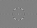
Within visual perception, an optical illusion (also called a visual illusion[2]) is an illusion caused by the visual system and characterized by a visual percept that arguably appears to differ from reality. Illusions come in a wide variety; their categorization is difficult because the underlying cause is often not clear[3] but a classification[1][4] proposed by Richard Gregory is useful as an orientation. According to that, there are three main classes: physical, physiological, and cognitive illusions, and in each class there are four kinds: Ambiguities, distortions, paradoxes, and fictions.[4] A classical example for a physical distortion would be the apparent bending of a stick half immerged in water; an example for a physiological paradox is the motion aftereffect (where, despite movement, position remains unchanged).[4] An example for a physiological fiction is an afterimage.[4] Three typical cognitive distortions are the Ponzo, Poggendorff, and Müller-Lyer illusion.[4] Physical illusions are caused by the physical environment, e.g. by the optical properties of water.[4] Physiological illusions arise in the eye or the visual pathway, e.g. from the effects of excessive stimulation of a specific receptor type.[4] Cognitive visual illusions are the result of unconscious inferences and are perhaps those most widely known.[4]
Pathological visual illusions arise from pathological changes in the physiological visual perception mechanisms causing the aforementioned types of illusions; they are discussed e.g. under visual hallucinations.
Optical illusions, as well as multi-sensory illusions involving visual perception, can also be used in the monitoring and rehabilitation of some psychological disorders, including phantom limb syndrome[5] and schizophrenia.[6]
https://en.wikipedia.org/wiki/Optical_illusion


https://en.wikipedia.org/wiki/Optical_illusion
This is a list of visual illusions.
| Name | Example | Notes |
|---|---|---|
| Afterimageillusion |  | An afterimage or ghost image is a visual illusion that refers to an image continuing to appear in one's vision after the exposure to the original image has ceased. |
| Afterimage on empty shape(also known as color dove illusion) |  | This type of illusions is designed to exploit graphical similarities. |
| Ambiguous image |  | These are images that can form two separate pictures. For example, the image shown forms a rabbit and a duck. |
| Ambigram | .gif) | A calligraphic design that has several interpretations as written. |
| Ames roomillusion |  | An Ames room is a distorted room that is used to create a visual illusion. |
| Ames trapezoid window illusion |  | A window is formed in the shape of a trapezium. It is often hung and spun around to provide the illusion that the window rotates through less than 180 degrees. |
| Autokinetic effect | The autokinetic effect, or autokinesis, occurs when a stationary image appears to move. | |
| Autostereogram |   | An autostereogram is a single-image stereogram (SIS), designed to create the visual illusion of a three-dimensional (3D) scene from a two-dimensional image in the human brain. An ASCII stereogram is an image that is formed using characters on a keyboard. Magic Eye is an autostereogram book series. |
| Barberpole illusion |  | The barber pole illusion is a visual illusion that reveals biases in the processing of visual motion in the human brain. |
| Benham's top |  | When a disk that has lines or colours on it is spun, it can form arcs of colour appear. |
| Beta movement | Movement that appears to occur when fixed pictures turn on and off. | |
| Bezold Effect |  | An apparent change of tone of a colour due to the alteration of the colour of the background. |
| Blivet |  | Also known as "poiuyt" or "devil's fork", this illusion is an impossible image because in reality the shape cannot exist. |
| Café wall illusion |  | This illusion is a pattern where different coloured squares on a wall appear to form horizontal curved lines. It is named such because this is the type of artwork often seen on café walls. |
| Catoptric cistula |  | A catoptric cistula is a box with insides made of mirrors so as to distort images of objects put into the box. |
| Checker shadow illusion |   | The checker shadow illusion shows that when a shadow is cast onto a checked board, the colours of squares A and B in the photos appear to be different, when in fact they are the same. |
| Chubb illusion |  | The Chubb illusion is an optical illusion or error in visual perception in which the apparent contrast of an object varies substantially to most viewers depending on its relative contrast to the field on which it is displayed. |
| Color constancy |  | Colour constancy is an example of subjective constancy and a feature of the human color perception system which ensures that the perceived color of objects remains relatively constant under varying illumination conditions. A green apple for instance looks green to us at midday, when the main illumination is white sunlight, and also at sunset, when the main illumination is red. |
| Color phi phenomenon | The color phi phenomenon is a perceptual illusion in which a disembodied perception of motion is produced by a succession of still images. | |
| Contingent perceptual aftereffect | ||
| Convergence micropsia | ||
| Cornsweet illusion |  | An illusion where two colours can obviously be seen to be different when placed directly beside each other; however, when the two colours are separated by a thick black line, they appear to be of the same hue. |
| Delboeuf illusion |  | An optical illusion of relative size perception. The two black circles are exactly the same size; however, the one on the left seems larger. |
| Disappearing Model | A trompe-l'œil body painting by Joanne Gair. | |
| Ebbinghaus illusion |  | The Ebbinghaus illusion, or Titchener circles, is an optical illusion of relative size perception. The two orange circles are exactly the same size; however, the one on the right appears larger. |
| Ehrenstein illusion |   | The Ehrenstein illusion is an optical illusion studied by the German psychologist Walter Ehrenstein in which the sides of a square placed inside a pattern of concentric circles take an apparent curved shape. |
| Fechner color | ||
| Figure-ground (perception) |  | |
| Filling-in |  | |
| Flash lag illusion | ||
| Forced perspective |  | Application used in film and architecture to create the illusion of larger, more distant objects. |
| Fraser spiral illusion |  | The Fraser spiral illusion, or false spiral, or the twisted cord illusion, was first described by the British psychologist Sir James Fraser in 1908. The overlapping black arc segments appear to form a spiral; however, the arcs are a series of concentric circles. |
| Gravity hill | ||
| Grid illusion |   | Any kind of grid that deceives a person's vision. The two most common types of grid illusions are the Hermann grid illusion (1870) and the scintillating grid illusion (1994). The first is characterized by "ghostlike" grey blobs perceived at the intersections of a white (or light-colored) grid on a black background. The grey blobs disappear when looking directly at an intersection. The second is constructed by superimposing white discs on the intersections of orthogonal gray bars on a black background. Dark dots seem to appear and disappear rapidly at random intersections, hence the label "scintillating". When a person keeps their eyes directly on a single intersection, the dark dot does not appear. The dark dots disappear if one is too close to or too far from the image. |
| Hering illusion |  | The Hering illusion (1861): When two straight and parallel lines are presented in front of radial background (like the spokes of a bicycle), the lines appear as if they were bowed outwards. |
| Hollow-Face illusion |  | The Hollow-Face illusion is an optical illusion in which the perception of a concave mask of a face appears as a normal convex face. |
| Hybrid image |  | A Hybrid image is an optical illusion developed at MIT in which an image can be interpreted in one of two different ways depending on viewing distance. |
| Illusory contours |  | Illusory contours or subjective contours are a form of visual illusion where contours are perceived without a luminance or color change across the contour. |
| Impossible object |  | |
| Irradiation illusion | ||
| Isometric illusion |  | An isometric illusion (also called an ambiguous figure or inside/outside illusion) is a type of optical illusion, specifically one due to multistable perception. |
| Jastrow illusion |  | The Jastrow illusion is an optical illusion discovered by the American psychologist Joseph Jastrow in 1889. |
| Kanizsa triangle | | The Kanizsa triangle is an optical illusion first described by the Italian psychologist Gaetano Kanizsa in 1955. It is a triangle formed of illusory contours. |
| Kinetic Depth Effect | The Kinetic depth effect refers to the phenomenon whereby the three-dimensional structural form of a silhouette can be perceived when the object is moving. In the absence of other visual depth cues, this might be the only perception mechanism available to infer the object's shape. Additionally the direction of motion can reverse due to the existence of multiple 3D visual solutions. | |
| Leaning tower illusion | The Leaning tower illusion is an optical illusion that presents two identical images of the Leaning Tower of Pisa side by side. | |
| Lilac chaser |  | Lilac chaser is a visual illusion, also known as the Pac-Man illusion. |
| Liquid crystal shutter glasses | ||
| Lunar terminator illusion | Lunar terminator illusion is an optical illusion where the apparent source of sunlight illuminating the moon does not corresponding with the actual position of the sun. | |
| Mach bands |  | Mach bands is an optical illusion named after the physicist Ernst Mach. |
| McCollough effect |  | The McCollough effect (1965) is a phenomenon of human visual perception in which colorless gratings appear colored contingent on the orientation of the gratings. It is an aftereffect requiring a period of induction to produce it. |
| Missing square puzzle |   | The missing square puzzle is an optical illusion used in mathematics classes to help students reason about geometrical figures. |
| Moon illusion |  | The Moon illusion is an optical illusion in which the Moon appears larger near the horizon than it does while higher up in the sky. |
| Motion aftereffect | ||
| Motion illusion |  | |
| Müller-Lyer illusion |  | The Müller-Lyer illusion is an optical illusion consisting of a stylized arrow. |
| Multistability | ||
| Musion Eyeliner | ||
| Necker cube |  | The Necker cube is an optical illusion first published in 1832 by Swiss crystallographer Louis Albert Necker. |
| Numerosity adaptation effect |  | |
| Orbison illusion |  | The Orbison illusion is an optical illusion that was first described by the psychologist William Orbison in 1939. |
| Penrose stairs |  | The Penrose stairs was created by Lionel Penrose and his son Roger Penrose.[1] A variation on the Penrose triangle, it is a two-dimensional depiction of a staircase in which the stairs make four 90-degree turns as they ascend or descend yet form a continuous loop, so that a person could climb them forever and never get any higher. |
| Penrose triangle |  | The Penrose triangle was first created by the Swedish artist Oscar Reutersvärd in 1934. The mathematician Roger Penrose independently devised and popularised it in the 1950s, describing it as "impossibility in its purest form". |
| Pepper's ghost | ||
| Perceived visual angle |  | |
| Peripheral drift illusion |  | A motion illusion (1979/1999) generated by the presentation of a sawtooth luminance grating in the visual periphery. |
| Phantogram |  | Phantograms, also known as Phantaglyphs, Op-Ups, free-standing anaglyphs, levitated images, and book anaglyphs, are a form of optical illusion. |
| Phi phenomenon | ||
| Poggendorff illusion |  | The Poggendorff illusion (1860) involves the misperception of the position of one segment of a transverse line that has been interrupted by the contour of an intervening structure (here a rectangle). |
| Ponzo illusion |  | In the Ponzo illusion (1911) two identical lines across a pair of converging lines, similar to railway tracks, are drawn. The upper line looks longer because we interpret the converging sides according to linear perspective as parallel lines receding into the distance. In this context, we interpret the upper line as though it were farther away, so we see it as longer – a farther object would have to be longer than a nearer one for both to produce retinal images of the same size. |
| Pulfrich effect | The Pulfrich effect is the effect that covering one eye with transparent but darkened glass can cause purely lateral motion to appear to have a depth component even though in reality it doesn't; even a completely flat scene such as one shown on a television screen can appear to exhibit some three-dimensional motion, but this is an illusion due to the fact that darkening the scene for one eye causes the photoreceptors in that eye to respond more slowly. | |
| Rubin vase |  | Rubin vase (1915): an ambiguous or bi-stable (i.e., reversing) two-dimensional form. |
| Sander illusion | In Sander's parallelogram (1926) the diagonal line bisecting the larger, left-hand parallelogram appears to be considerably longer than the diagonal line bisecting the smaller, right-hand parallelogram, but is in fact the same length. | |
| Silencing |  | Silencing is an illusion in which a set of objects that change in luminance, hue, size, or shape appears to stop changing when it moves. |
| Size–weight illusion | The size–weight illusion is also known as the Charpentier illusion or Charpentier–Koseleff illusion. | |
| Stepping feet illusion | The stepping feet illusion is influenced by the contrast between moving objects and their background. | |
| Stroboscopic effect | ||
| Swept-plane display | ||
| Ternus illusion | The Ternus illusion (1926/1938) is based upon apparent motion. | |
| Thaumatrope |  | A thaumatrope is a toy that was popular in Victorian times. |
| Trompe-l'œil | ||
| Troxler's fading | Troxler's fading: When one fixates on a particular point for even a short period of time, an unchanging stimulus away from the fixation point will fade away and disappear. | |
| Vertical–horizontal illusion |  | The Vertical-horizontal illusion is the tendency for observers to overestimate the length of a vertical line relative to a horizontal line of the same length. |
| Visual tilt effects |   | |
| Wagon-wheel effect |  | |
| White's illusion |  | |
| Wundt illusion |  | The two red vertical lines are both straight, but they may look as if they are bowed inwards to some observers. The distortion is induced by the crooked lines on the background |
| Zoetrope |  | |
| Zöllner illusion |  | The Zöllner illusion is a classic optical illusion named after its discoverer, German astrophysicist Johann Karl Friedrich Zöllner. |
See also[edit]
- Adaptation (eye)
- Alice in Wonderland syndrome
- Auditory illusion
- Camouflage
- Contingent perceptual aftereffect
- Contour rivalry
- Depth perception
- Emmert's law
- Entoptic phenomenon
- Gestalt psychology
- Infinity pool
- Kinetic depth effect
- Mirage
- Multistable perception
- Op Art
In quantum field theory, a false vacuum[1] is a hypothetical vacuum that is stable, but not in the most stable state possible (it is metastable).[2] It may last for a very long time in that state, but could eventually decay to the more stable state, an event known as false vacuum decay. The most common suggestion of how such a decay might happen in our universe is called bubble nucleation – if a small region of the universe by chance reached a more stable vacuum, this "bubble" (also called "bounce")[3][4] would spread.
A false vacuum exists at a local minimum of energy and is therefore not stable, in contrast to a true vacuum, which exists at a global minimum and is stable.
https://en.wikipedia.org/wiki/False_vacuum_decay
The photoelectric effect is the emission of electrons when electromagnetic radiation, such as light, hits a material. Electrons emitted in this manner are called photoelectrons. The phenomenon is studied in condensed matter physics, and solid state and quantum chemistry to draw inferences about the properties of atoms, molecules and solids. The effect has found use in electronic devices specialized for light detection and precisely timed electron emission.
The experimental results disagree with classical electromagnetism, which predicts that continuous light waves transfer energy to electrons, which would then be emitted when they accumulate enough energy. An alteration in the intensity of light would theoretically change the kinetic energy of the emitted electrons, with sufficiently dim light resulting in a delayed emission. The experimental results instead show that electrons are dislodged only when the light exceeds a certain frequency—regardless of the light's intensity or duration of exposure. Because a low-frequency beam at a high intensity could not build up the energy required to produce photoelectrons, as it would have if light's energy were coming from a continuous wave, Albert Einstein proposed that a beam of light is not a wave propagating through space, but a swarm of discrete energy packets, known as photons.
Emission of conduction electrons from typical metals requires a few electron-volt (eV) light quanta, corresponding to short-wavelength visible or ultraviolet light. In extreme cases, emissions are induced with photons approaching zero energy, like in systems with negative electron affinity and the emission from excited states, or a few hundred keV photons for core electrons in elements with a high atomic number.[1] Study of the photoelectric effect led to important steps in understanding the quantum nature of light and electrons and influenced the formation of the concept of wave–particle duality.[2] Other phenomena where light affects the movement of electric charges include the photoconductive effect, the photovoltaic effect, and the photoelectrochemical effect.
https://en.wikipedia.org/wiki/Photoelectric_effect
Jonas Ferdinand Gabriel Lippmann[2] (16 August 1845 – 13 July 1921) was a Franco-Luxembourgish physicist and inventor, and Nobel laureate in physics for his method of reproducing colours photographically based on the phenomenon of interference.[3]
Lippmann made several important contributions to various branches of physics over the years.

The capillary electrometer[edit]
One of Lippmann's early discoveries was the relationship between electrical and capillary phenomena which allowed him to develop a sensitive capillary electrometer, subsequently known as the Lippmann electrometer which was used in the first ECG machine. In a paper delivered to the Philosophical Society of Glasgow on 17 January 1883, John G. M'Kendrick described the apparatus as follows:
- Lippmann's electrometer consists of a tube of ordinary glass, 1 metre long and 7 millimetres in diameter, open at both ends, and kept in the vertical position by a stout support. The lower end is drawn into a capillary point, until the diameter of the capillary is .005 of a millimetre. The tube is filled with mercury, and the capillary point is immersed in dilute sulphuric acid (1 to 6 of water in volume), and in the bottom of the vessel containing the acid there is a little more mercury. A platinum wire is put into connection with the mercury in each tube, and, finally, arrangements are made by which the capillary point can be seen with a microscope magnifying 250 diameters. Such an instrument is very sensitive; and Lippmann states that it is possible to determine a difference of potential so small as that of one 10,080th of a Daniell. It is thus a very delicate means of observing and (as it can be graduated by a compensation-method) of measuring minute electromotive forces.[9][10]
Lippmann's PhD thesis, presented to the Sorbonne on 24 July 1875, was on electrocapillarity.[11]
Piezoelectricity[edit]
In 1881, Lippmann predicted the converse piezoelectric effect.[12]
Colour photography[edit]

Above all, Lippmann is remembered as the inventor of a method for reproducing colours by photography, based on the interference phenomenon, which earned him the Nobel Prize in Physics for 1908.[7]
In 1886, Lippmann's interest turned to a method of fixing the colours of the solar spectrum on a photographic plate. On 2 February 1891, he announced to the Academy of Sciences: "I have succeeded in obtaining the image of the spectrum with its colours on a photographic plate whereby the image remains fixed and can remain in daylight without deterioration." By April 1892, he was able to report that he had succeeded in producing colour images of a stained glass window, a group of flags, a bowl of oranges topped by a red poppy and a multicoloured parrot. He presented his theory of colour photography using the interference method in two papers to the Academy, one in 1894, the other in 1906.[5]

-02.jpg)
The interference phenomenon in optics occurs as a result of the wave propagation of light. When light of a given wavelength is reflected back upon itself by a mirror, standing waves are generated, much as the ripples resulting from a stone dropped into still water create standing waves when reflected back by a surface such as the wall of a pool. In the case of ordinary incoherent light, the standing waves are distinct only within a microscopically thin volume of space next to the reflecting surface.
Lippmann made use of this phenomenon by projecting an image onto a special photographic plate capable of recording detail smaller than the wavelengths of visible light. The light passed through the supporting glass sheet into a very thin and nearly transparent photographic emulsion containing sub microscopically small silver halide grains. A temporary mirror of liquid mercury in intimate contact reflected the light back through the emulsion, creating standing waves whose nodes had little effect while their antinodes created a latent image. After development, the result was a structure of laminae, distinct parallel layers composed of submicroscopic metallic silver grains, which was a permanent record of the standing waves. In each part of the image, the spacing of the laminae corresponded to the half-wavelengths of the light photographed.
The finished plate was illuminated from the front at a nearly perpendicular angle, using daylight or another source of white light containing the full range of wavelengths in the visible spectrum. At each point on the plate, light of approximately the same wavelength as the light which had generated the laminae was strongly reflected back toward the viewer. Light of other wavelengths which was not absorbed or scattered by the silver grains simply passed through the emulsion, usually to be absorbed by a black anti-reflection coating applied to the back of the plate after it had been developed. The wavelengths, and therefore the colours, of the light which had formed the original image were thus reconstituted and a full-colour image was seen.[13][14][15]
In practice, the Lippmann process was not easy to use. Extremely fine-grained high-resolution photographic emulsions are inherently much less light-sensitive than ordinary emulsions, so long exposure times were required. With a lens of large aperture and a very brightly sunlit subject, a camera exposure of less than one minute was sometimes possible, but exposures measured in minutes were typical. Pure spectral colours reproduced brilliantly, but the ill-defined broad bands of wavelengths reflected by real-world objects could be problematic. The process did not produce colour prints on paper and it proved impossible to make a good duplicate of a Lippmann colour photograph by rephotographing it, so each image was unique. A very shallow-angled prism was usually cemented to the front of the finished plate to deflect unwanted surface reflections, and this made plates of any substantial size impractical. The lighting and viewing arrangement required to see the colours to best effect precluded casual use. Although the special plates and a plate holder with a built-in mercury reservoir were commercially available for a few years circa 1900, even expert users found consistent good results elusive and the process never graduated from being a scientifically elegant laboratory curiosity. It did, however, stimulate interest in the further development of colour photography.[15]
Lippmann's process foreshadowed laser holography, which is also based on recording standing waves in a photographic medium. Denisyuk reflection holograms, often referred to as Lippmann-Bragg holograms, have similar laminar structures that preferentially reflect certain wavelengths. In the case of actual multiple-wavelength colour holograms of this type, the colour information is recorded and reproduced just as in the Lippmann process, except that the highly coherent laser light passing through the recording medium and reflected back from the subject generates the required distinct standing waves throughout a relatively large volume of space, eliminating the need for reflection to occur immediately adjacent to the recording medium. Unlike Lippmann colour photography, however, the lasers, the subject and the recording medium must all be kept stable to within one quarter of a wavelength during the exposure in order for the standing waves to be recorded adequately or at all.
Integral photography[edit]
In 1908, Lippmann introduced what he called "integral photography", in which a plane array of closely spaced, small, spherical lenses is used to photograph a scene, recording images of the scene as it appears from many slightly different horizontal and vertical locations. When the resulting images are rectified and viewed through a similar array of lenses, a single integrated image, composed of small portions of all the images, is seen by each eye. The position of the eye determines which parts of the small images it sees. The effect is that the visual geometry of the original scene is reconstructed, so that the limits of the array seem to be the edges of a window through which the scene appears life-size and in three dimensions, realistically exhibiting parallax and perspective shift with any change in the position of the observer.[16] This principle of using numerous lenses or imaging apertures to record what was later termed a light field underlies the evolving technology of light-field cameras and microscopes.
When Lippmann presented the theoretical foundations of his "integral photography" in March 1908, it was impossible to accompany them with concrete results. At the time, the materials necessary for producing a lenticular screen with the proper optical qualities were lacking. In the 1920s, promising trials were made by Eugène Estanave, using glass Stanhope lenses, and by Louis Lumière, using celluloid.[17] Lippmann's integral photography was the foundation of research on 3D and animated lenticular imagery and also on color lenticular processes.
Measurement of time[edit]
In 1895, Lippmann evolved a method of eliminating the personal equation in measurements of time, using photographic registration, and he studied the eradication of irregularities of pendulum clocks, devising a method of comparing the times of oscillation of two pendulums of nearly equal period.[4]
The coelostat[edit]
Lippmann also invented the coelostat, an astronomical tool that compensated for the Earth's rotation and allowed a region of the sky to be photographed without apparent movement.[4]
Academic affiliations[edit]
Lippmann was a member of the Academy of Sciences from 8 February 1886 until his death, serving as its president in 1912.[18] In addition, he was a Foreign Memberof the Royal Society of London, a member of the Bureau des Longitudes,[4] and a member of the Grand Ducal Institute of Luxembourg. He became a member of the Société française de photographie in 1892 and its president from 1896 to 1899.[19] Lippmann was one of the founders of the Institut d'optique théorique et appliquée in France. Lippmann was the President of the Société Astronomique de France (SAF), the French astronomical society, from 1903–1904.[20]
https://en.wikipedia.org/wiki/Gabriel_Lippmann
Louis Jean Lumière (5 October 1864 Besançon – 6 June 1948, Bandol)[1] was a French engineer and industrialist who played a key role in the development of photography and cinema.
Early life and education[edit]
Lumière was one of four children of Claude-Antoine Lumière, a photographer and painter, and his wife Jeanne-Joséphine (née Costille). He attended the Martinière Technical School and placed first in his class.[1]
Career[edit]
At age 17, Lumière invented a new process for film development using a dry plate. This process was significantly successful for the family business, permitting the opening of a new factory with an eventual production of 15 million plates per year.[2] Thomas Edison's Kinetoscope inspired his and his brother's subsequent work on the cinematograph.[3]
Louis Lumière is most often associated with the name of his brother, Auguste Lumière, under the name of the Lumière brothers. This comparison is a little excessive with regard to the invention of the cinematograph, since in reality, Auguste failed in his attempt to manufacture the first machine, and passed it to his brother who made the invention succeed. On the other hand, Louis was the director of all the first animated photographic views of the Lumière Society, which Auguste sometimes attended only as an amateur actor (Le Repas de bébé, La Pêche aux poissons rouges, Démolition d'un mur, etc.). But the contract signed between the two brothers provided that they be systematically associated, both morally and financially, in all their work and discoveries.
https://en.wikipedia.org/wiki/Louis_Lumière
No comments:
Post a Comment